Optomechanics – Flexures

Colleagues:

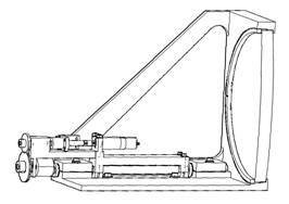
Well, with Summer around the corner this may be my last chance to tickle your consciousness before the lazy days set in.  My subject this time is broken flexures, specifically broken double cantilever blade flexures of the sort shown:
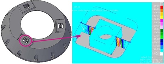
I have long been reluctant to use this type of flexure because the double cantilever beam, being restrained on both ends, is not well described by linear elastic structural theory.  Rather than study the problem I’ve just avoided it, until now.  The difference between now and then is that a friend has some broken double cantilever blade flexures now and has sought my counsel.  Well, one thing leads to another and here I am:  With a friend who has broken flexures.  Way back then broken double cantilever blade flexures were less personal, just conjectural.  I was able to avoid the whole issue.  But, now is now so here I go.

The “problem” with the double cantilever beam, and the flexures that rely on its mechanics, is they don’t fit “well” into the small displacement linear elastic theory that is usually used to analyze them for strength and stiffness.  As I will show it all depends upon what you may call a “small displacement.”

As you deflect the double cantilever beam flexure by applying a load in the center, the center will deflect and the length of the beam will increase, at first slowly and then faster and faster.  This increase in length creates axial forces and tensile stresses in the beam (flexure).  This increase in length is a second order effect in the differential equations and therefore ignored by the small displacement linear elastic theory.  The Euler-Bernouli beam theory agrees with the finite element method that these tensile forces and stresses do not exist.  But intuitively they have to be there.  How severe is this discrepancy?

I take as my starting point some earlier work (Hatheway, SPIE, 3132-19, 1997) on the radius of curvature of the locus of the end point of a cantilever beam.  This permits the calculation of the foreshortening of a free cantilever beam, which would be equal to, and opposite in sense to, the stretching in a constrained cantilever beam.  With this information I was able to estimate the forces and stresses attributable to the stretching of the beam (flexure).  These need to be added to the Euler-Bernouli results.  They are shown in the following chart, the vertical axis of which presents a ratio which is the sum of the Euler-Bernouli bending effect and the non-linear stretching effect divided by the Euler-Bernouli bending effect alone.  The magnitude of the ratio is shown for both stress effects and force resultant effects.  The horizontal axis is the deflection of the flexure as a multiple of the thickness of the flexure’s blade.
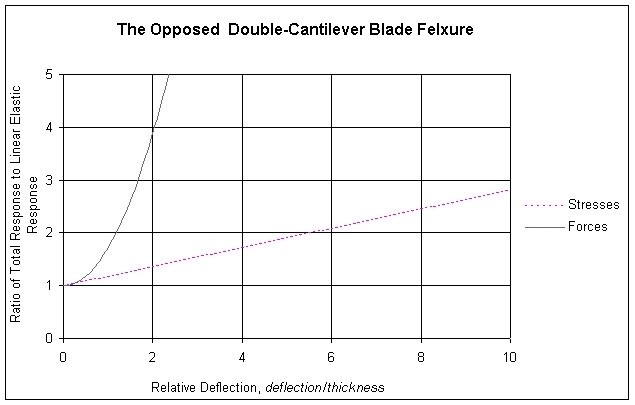
As you may observe the stresses and forces agree reasonably well with the linear elastic stresses and forces when the deflections (and therefore the Relative Deflections) are very small, approaching zero.  When the deflection approaches the thickness of the blade (Relative Deflection equal to 1.0) the state of stress is about 18% higher (Ratio=1.18) than the linear elastic stresses alone and the reaction force is about 72% higher (Ratio=1.72) than the linear elastic bending load alone.  From there the values increase, the force values quite rapidly.

Thus, for a given deflection the designer may estimate the total force and the total tensile stress in the flexure:  First, from the required deflection, calculate the linear elastic values for stress and force from conventional beam theory (or a finite element model).  Then multiply these by the factors from the chart.  These are still “small displacement” results, but “nonlinear” as you can see, incorporating only one higher order or higher degree term in the solution.  (A caution:  It is not at all clear that these are valid all the way out to a Relative Deflection of 10.  Other higher order terms surely will contribute somewhere in this range.)  One open question is then, “Just how small is the small displacement domain?”  One answer might be based upon desired accuracy.  Another might just seek to satisfy some required Factor of Safety.  Obviously, if the displacements are small enough one needn’t worry about non-linear effects (Or any effects at all, a wag might point out!).

Well, that’s kinda’ what I’ve been up to this Springtime.  And now, with the weather warming up and a fresh tube of sun-block I’m ready to let you go. 

But first —  I’ve been invited to address the Optical Society of Southern California (OSSC) at their dinner meeting on June 23rd.  My subject will be “Applying the Arts of Structural Engineering to Optics.”  It is an open meeting, anyone may attend, but you must make reservations if you’ll be there for dinner.  I promise to be more entertaining than this dry missive.

For reservations go to

http://www.ossc.org

The meeting will be at Luminaria’s Restaurant in Monterey Park, near the intersection of Interstate 10 and Interstate 710.  I expect to be challenged on the relevance of the “linear small displacement domain,” other charming topics and I look forward to a vigorous discussion.  Hope to see you all there.

Al H.
6-7-10

Optomechanics – Evidence!

Colleagues (again):

Ask and thou shalt receive!

I am now in receipt of a genuine photograph of a genuine failure of a glass lens in a metal ring mount.  It was in a laser cavity and failed (fractured) during high rep-rate operation.  The engineer avers that “there may also [have been] some stress concentration in the mount such as a burr or particle” but he feels they solved the problem by replacing the clamping ring with a fillet of adhesive.  Good show!

I pass this along to you because I know there have to be problems out there with ring-mounted glass lens assemblies.  I was beginning to think no one was reading my correspondence (and that hurt my feelings!).  Now that I feel better, I’ll stay out of your mailboxes for a while.

I also want to honor the engineer who sent this example in.  Broken glass is not pretty and sometimes it takes courage to talk or write about it.

Al H.
9-2-09

Optomechanics – The Myth of the Ring-Mounted Glass Lens Fracture

Colleagues:

Some of you may remember a survey I conducted a couple of years ago concerning the fracture of ring-mounted glass lenses.  Of the 300 or so optical professionals queried (OSSC and SPIE members, mostly) not one had first-hand experience in such a mounting failure.  Several expressed grave concern and one or two had heard stories that they felt were creditable.  This group must have personally guided thousands of lens mount designs.  And not a single fractured lens among them.  This basically validated my experience:  I’ve never had a ring-mounted glass lens fracture because of its mounting.

The anomaly here was that the accepted structural theory (Delgado and Hallinan, Opt. Eng. 14, S11, 1975) predicted very high tensile stresses in the lenses, especially at low temperatures when the metal contracts more than the glass.  Many failures should have been reported, especially in the military sector where low temperature operation is required.

The good news is that the accepted structural theory was wrong.  Those authors accepted that the contact between a sphere and a flat plane is the same as the contact between a ring and a flat plane.  The stresses in the sphere-on-plane case had been solved by others whereas the stresses in the ring-on-plane case would take some additional development effort.

Now, the ring-on-plane case has been solved (Hatheway, Proceedings of SPIE, 7424-14, 2009) for the surface tensile stresses that may cause fracture. 

For comparison lets take a lens cell I designed a short while ago.  The lens is 10 cm diameter and needs a ring compression load of 77.3 N to secure it against a shock load of 20 gs. 

The peak tensile stress according to the sphere-on-plane theory is

s=15,300,000 Pa (2,238 psi)                             (Delgado and Hallinan)

and the peak tensile stress for the ring-on-plane theory is

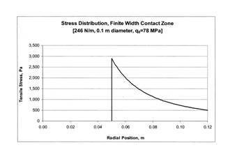
s=2,893 Pa (0.422 psi)                                  (Hatheway)

a ratio of 5,300:1, almost four orders of magnitude.  The higher level (2,238 psi) is enough to cause fracture in a short period of time (about three minutes).  The lower level (0.422 psi) would provide a lifetime longer than the engineer who designed it (10.3 x 10¹⁴ years) and possibly account for the lack of witnesses in my survey, above.

Those of you interested in the gory details can download my paper from the SPIE website.  Please don’t ask me for copies because I’ve signed the copyright over to SPIE.  However, as a consolation prize for reading this email all the way through I’ll give you the answer:

Peak tensile stress=P(1-2u)/2pr2

where P=ring loading (dimensions of force), u=Poisson’s ratio (dimensionless) and r=radius of the ring contact (dimensions of length).

Well, Summer was very mild in Southern California until the fire season broke out, in spades.  It looks like we’ll make it through this spate OK but that season is just beginning for us. 

Here’s wishing us all a terrific Autumn and getting the little ones back to school.  And here’s to all that broken glass that didn’t happen, this time.

Al H.
8-31-09

Optomechanics – Adhesives

Dear Colleagues:

Let me ask you a really silly question:  “Do any of you have adhesive problems?”

OK, enough funny stuff.  Let me ask you a more serious question:  “Do any of you not have adhesive problems?”

In this practitioner’s experience adhesive problems are ubiquitous.  And the bad news is that fully two-thirds of these problems are not the adhesives’ fault!  Let me explain, please.

Most of the people who ask my help correcting an adhesive bond failure cannot answer this simple question, “Is it a cohesion failure or an adhesion failure?”  A knowledgeable response may require inspection of the surfaces, perhaps with a 3x magnifying glass.  A cohesion failure is represented by fracture of the bulk adhesive in the bonded joint while the adhesive stays attached to the two opposing surfaces.  An adhesion failure is represented by the adhesive separating from one or both surfaces leaving little or no adhesive residue on the surfaces. 

The significance of the answer to “the question” is that it points to one of two mutually exclusive approaches to preventing future failures.  A cohesion failure has two possible causes:  Defective material from the supplier or defective mixing and/or curing procedures by the user.  An adhesion failure has only one cause:  Defective surface preparation by the user.  This assumes of course that the adhesive was adequately screened for cured strength properties and compatibility with the materials being bonded together.

There are three parts to an adhesive joint design problem.  The first two are the surfaces to be bonded together.  The third is the adhesive used in the process.

Adhesive suppliers attempt to manufacture a raw material (say, a polymer with a curing agent) that when mixed, applied, cured (and whatever else) in accordance with the manufacturers’ data sheets will provide physical properties that agree with those advertised for the product.  Think of it as a steel ingot emerging from a Bessemer furnace.  This ingot is still not a steel structure (such as a baseball stadium).  It needs to be formed (into sheet or plate, rolled into beams, cast or forged into fittings, etc.).  Then the formed parts (near-net-shape in optical parlance) need to be cut to the right size, drilled and fastened (bolted, welded, riveted) into the structure.  Everyone who has engineered steel structures (or any metal structures at all) knows that each step of this process from steel ingot to finished stadium is carefully controlled, inspected and/or tested along the way in order to assure safety.

Let me contrast this to the way that many people use adhesives.  I’ll tell you about some real life adventures in adhesives-land—

I got a call from a client who wanted a finite element model of a simple structure to evaluate the stresses therein.  It turned out that what they really wanted was “a solution to an adhesives problem.”  OK.  I asked them “the question” and they couldn’t answer it.  I asked to inspect some failed parts but they had all been cleaned and put back in stock.  (The nature of the failure, adhesion versus cohesion, can usually be quickly determined by a cursory examination of the failed parts.)

Their design was pretty simple and I suggested that a longhand analysis using free-body diagrams would provide information just as good as a finite element model.  They insisted on a finite element analysis, which I performed (luckily it agreed well with the longhand numbers I had all ready run on the back of an envelope, literally).  So, with the stress numbers in hand we decided that the advertised strength of the adhesive was adequate.  We looked at the materials being bonded and they were common enough.  The client scratched his head in frustration and ordered a new search by his materials engineers for another adhesive.  I had seen their previous search results and suspected that there were very few alternative materials that could do this job (it required a couple of peculiar properties in the adhesive).

I took the design engineer aside and quizzed him.  “How was the bonding job done?”  “I don’t know.”  “Who did it?”  “The technician.”  We went to the lab and found the technician and I asked him to assemble another unit.  He and the engineer went to work while quietly, off to the side, I took notes.  When curing was complete we tested the bond joint for strength and it passed.  I gave the engineer my notes and told him to put an engineering drawing number on them and make them required reading by any person who will perform future bonding operations.  Here are my notes:

“Technician got a clean shop coat.
“Technician got clean gloves.
“Parts stored in vinyl bags prior to bonding.
“Technician wipes base on sleeve of shop coat.
“Fresh syringe of adhesive opened.
“Technician applies adhesive to base.
“Technician wipes flange on opposite sleeve of shop coat.
“Technician presses the flange into the adhesive on the base.
“Engineer applies UV light to joint for 45 seconds.
“Engineer inspects bond joint for uniformity.”

I never found out the results of their search for another adhesive but I have seen trucks backed-up to their shipping dock hauling their products to market.

Returning from adhesives-land to the here-and-now—

Some practitioners will declare that process control is not that easy.  They are somewhat right.  In the industries that are seriously concerned with public safety (like civil aircraft) they are certainly right. 

My response is that controlling a process is not necessarily very difficult.  Also, that it is amazing what a difference it can make to pay a little attention to just a few details, even if they may not be the essential details in themselves.  For instance, having the engineer and myself present made the technician sufficiently self conscious to get a clean shop coat and clean gloves, caused him to clean the surfaces on different (presumably clean) parts of his shop coat and stimulated a conversation about the appropriate exposure time arriving at an agreement on 45 seconds to begin with, which proved sufficient in the circumstance.

The reticence to controlling adhesive bonding processes is not limited to small firms, start-ups and consumer products.  I see many of the same attitudes (and problems) in the R&D branches of the big aerospace and defense industry.  Researchers, bless their hearts, require a less disciplined environment in order to express their creativeness. 

My message to all of you is that people who use adhesives ought to take responsibility for the two-thirds of the bonded joint assembly process that you can control.  Write down your method, test the results and require the method to be used by everyone.  Until you have attempted to take control of the application process, in even as simple a form as my parable suggests, it is very premature to blame the adhesive.

The wags among you may exclaim,”What does this have to do with optomechanics?”  Well, the above example was actually a cemented doublet.

I hope all of you are enjoying the thrill of Springtime! 

Here we go again. 

Isn’t it awesome?

Al Hatheway
6-2-09

Optomechanics – Lots of Trainings

Colleagues:

The cooling of the weather is a clear indication that Winter is coming, not withstanding the wild fires we’ve recently had here in Southern California. All of the holidays from Thanksgiving to Valentine’s Day are just around the corner. Here are a few items on my agenda for next year:

Once again I’ll be teaching my one-day short course,

Optomechanical Analysis

830 AM to 500 PM
January 27, 2009

in San Jose during SPIE’s Photonics West Symposium. You may learn more about the course content and register to attend by clicking on the following exciting link;

http://spie.org/app/program/index.cfm?fuseaction=COURSE&export_id=x12502&ID=x6771&redir=x6771.xml&course_id=E0846163&event_id=795339&programtrack_id=848771


In April I’ll be teaching another short course,

Optomechanics and the Tolerancing of Instruments

in Orlando during SPIE’s Defense and Security Symposium. More on this later.


Next summer in San Diego we’ll have our two-day conference,

Advances in Optomechanics

During SPIE’s Optics and Photonics Symposium. This will include an evening meeting of the International Technical Group on Optomechanics.


I look forward to a great year. I hope you enjoy the Holiday Season and perhaps I’ll see you in San Jose in a few weeks.

Al Hatheway
11-25-08

Optomechanics – Ivory Predicts

Colleagues:

My Heavens!  Off axis systems are everywhere.  Are we having fun yet?

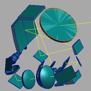
They pose extraordinary challenges to the optomechanical engineer.  With their diverse types of elements (reflective, diffractive, refractive), wide transmission bands (UV to far IR) and multiple focal plane arrays it almost seems perverse to complain that there is insufficient room for the metering structures (you know, optical benches and that kind of stuff).  In one recent job (34 optical elements and three image planes) the optical bench was just superb, but the inner gimbal ring was so flimsy that it was not possible to point the marvelous instrument at anything useful.  It became necessary to rob some mass and volume from the optical bench in order to stiffen the gimbal ring.  Essentially, the gimbal ring and the optical bench had to be designed and analyzed concurrently in order to stabilize the entire system.

I have found the Ivorytm Optomechanical Modeling Tools to be indispensable in the conceptual engineering of these systems.  The Optomechanical Constraint Equations provide the influence coefficients that identify the most sensitive elements and quantify their behavior.  The Unified Modeling utility supports the finite element models necessary as the work advances and the allocation of structural resources begins to freeze.  Ivory-based analyses provided the rational basis for trading gimbal ring stiffness against optical bench stiffness in the example above, creating an opportunity out of a crisis.

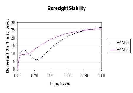
In another recent job the challenge was thermal stability of boresight among several instruments in severe environments.  I ran the complete mission profile (power dissipation, ambient temperatures, etc.) through the finite element code in thermal analysis mode.  These temperature vectors were then read into the Unified NASTRAN model (generated by my Ivory Optomechanical Modeling Tools) to calculate the boresight shift over the duration of a one-hour mission.

The good news is that Ivory-generated finite element models can provide accurate predictions for LOS and boresight in all the usual service environments.  The mechanical engineer just has to apply them early enough to claim sufficient space for the structures and other resources necessary to assure a stable system.  Too often it seems the analysis budget is committed after the mechanical design is essentially completed and a redesign becomes a financial crisis and sometimes a philosophical crisis as well.  I have found that Ivory-generated analyses often provide the engineer the credibility necessary for success in those early allocations of scarce resources in the tough projects.

Autumn is in the air here in Southern California.  I hope you all had as great a Summer as I have! 

It was good to see some of you in San Diego last month and it will be good to see others of you in San Jose come January.

Don’t forget about our conference in San Diego next August.  Get your manuscripts ready to go, the Call for Papers will be out in a couple of weeks.

Cheers! Keep the good stuff rolling.

Al H.
9/26/08

Optomechanics – Precision

Dear Colleague:

How accurately can your shop position a lens?

That is a question I’ve asked my students ever since I started teaching a class on optomechanical tolerancing of instruments, ca. 1990.  It’s amazing, the answers I’ve gotten.

It recurred again recently with a client who had a contract to produce a number of ultra-wide field imaging instruments.  The lens was composed of 19 glass elements arranged in nine singlets, four cemented doublets and two cemented triplets.  The optical prescription was supplied by their customer as were the allowable alignment tolerances:  ±0.005 mm in Tx, Ty and Tz and 20 arc-sec in Rx and Ry.

First, we had to establish the accuracy of their in-house fabrication processes.  Getting the crib-notes out of the technicians was real sport.  Then we had to find out the accuracy of their suppliers.  The latter is usually much more problematic since you don’t really find out anything until you try to negotiate a contract (or, worst-case, only when the parts are delivered).  Finally, we had to incorporate alignment mechanisms to make up the deficits, whatever we thought they may be.

You can put it all in a spreadsheet and have great fun with it!

Also back in the ’90s, I was asked by one of the shakers-‘n’-movers in the optical industry if I would publish a summary of the state-of-the-art of achievable manufacturing accuracy for the various manufacturing processes.  It would be a great boon to the industry, he said, and indeed it would.  Unfortunately, manufacturing accuracy is not a fixed quantity.  Not only does it vary over time but also with geography, supplier and price (not to mention attitude).  And the variation with each of these is not always favorable.

In the above example one of my client’s suppliers (actually, their preferred machine shop) refused to adopt innovative techniques that could provide the required accuracy, presumably because they had committed to a price before they knew what was to be demanded of them.  Or maybe they didn’t have the confidence in the precision of their machine tools that I expected.  Or maybe they had too much work and this would disrupt their shop practices.  Who knows?

So, back to the spreadsheet and more fun!  Thumb the yellow pages and buyers’ guides.  Explore changes to the construction materials.  Re-tolerance the optics?  Call the customer?  In some ways good engineering resembles good accounting; keep pushing the numbers around until you find a workable combination.

That’s engineering, and one more amazing answer to that question.

Cheers.

Al Hatheway
5-22-08

Optomechanics – The Strength of Glass

Dear Colleagues:

I have recently been involved in lively discussions about the nature of glass as a structural material and how to predict its strength properties.  The fact is that glass is by nature one of the strongest materials on earth with a “native” tensile strength on the order of 500,000 psi, stronger than most high alloy tool steels.  So, I am asked, “Why do the glass suppliers say to keep the stresses under 1,000 psi?”  The answer is that, unlike steel, glass is completely brittle showing no perceptible plastic deformation whatever in it its fracture. 

The growth of cracks in stressed steel parts is arrested by the plastic deformations in the material at the tips of the cracks.  The plastic deformations produce a small radius at the tip of an otherwise sharp crack, thereby reducing the high concentrated stresses (by orders of magnitude) at the very tip of the crack.

The growth of cracks in stressed glass parts is not arrested since plastic deformation does not occur.  This does not mean however that the strength of glass is indeterminate, unknowable or a random property.  It does mean that you should expect that glass has slightly different behavior than the ductile structural materials like steel.

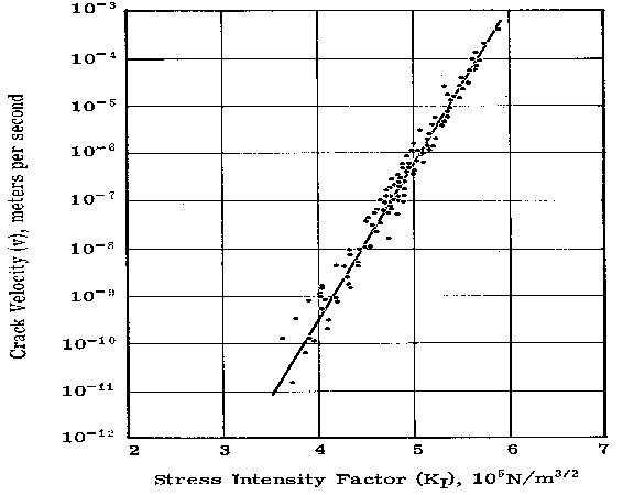
It has been shown by a number of researchers that under tensile stress a crack in glass will tend to grow in length (or depth) at a rate that is proportional to the nominal stress at the tip, s, and proportional to the square-root of its length, d.  To quantify the influences of stress and crack length on strength properties, structural engineers have developed a quantity known as the “stress intensity” that is usually represented by the character “K1.”  K1 includes a coefficient, a, that accounts for the geometric shape of the crack and is defined as,

K1 = s(ad)^.5

A crack propagation curve for fused silica is shown in the figure.

Other glasses may have different, even zig-zag, curve shapes.

It has also been shown by researchers that the crack will continue to grow in this predictable fashion until the stress intensity reaches a critical value, K1c, at which point the crack growth becomes unstable and proceeds rapidly to complete fracture without a velocity limit (except, perhaps, the speed of sound in the glass).  The critical stress intensity, K1c, is often published as the material strength property for a glass, ignoring the propagation effects above.

Glasses, especially optical glasses melted and cooled in a boule, are very uniform, isotropic and crack-free in their as-cooled state.  They exhibit the high “native” strength described above.  The cracks we are talking about here are all produced in subsequent fabrication processes: single point turning, grinding, polishing, etc., all of which produce sub-surface cracks that are about three time as deep as the diameter of the abrasive used in the process.  Polishing may remove visible grinding pits that are about as deep as the abrasive but may also leave behind invisible subsurface cracks that can still be twice as deep as the abrasive grinding grit.  “Controlled grinding and polishing” is the art of reducing and/or minimizing these residual subsurface cracks by special fabrication techniques.
 
So, this is the physics:  Ground and polished glass parts with structural stresses in them all have finite service lives because the cracks will grow continuously until complete fracture.  The lower the stress, the longer the life will be.  At 1,000 psi and with common optical finishing processes, the parts life may approach the human life span, sufficient for most cases and often recommended by glass suppliers.

As an engineer it is my practice, at higher stress levels, to integrate under the crack propagation curve to determine the acceptable fabricated crack length, d, in a glass part exposed to a known stress history and with a required service life.  The lower limit of integration is the stress intensity, K1i, at the initial as-fabricated crack length and the upper limit is the critical stress intensity, K1c.  This calculation provides the user with an assured minimum lifetime for his product.  It also lends itself to definition of non-destructive proof-testing for finished products to demonstrate the safe service life of each one. 

I perform the integration in custom software that I call Crystal
Crystal accommodates arbitrarily-shaped propagation curves and time-varying loading. 

One “snag” is that glass producers have not been encouraged to publish crack propagation curves for their glasses so the data are fairly sparse.  On the up-side however there is sufficient published data that a safe envelope for similar types of glass may often be assumed.
 
So, this is the engineering:  respect the physics and avoid broken glass.

Now…  Springtime is here and the snows will melt.  Yes, even in Spokane and Burlington!

Cheers. 

And no more broken glass!  OK?

Al H.
4-11-08

Optomechanics – Conduction in a Vacuum

Colleagues:

I recently completed an assignment to assist a client in the design of a low-cost high-performance cryogenic (LN2) dewar for infrared detectors.  The design include some powered optics as well as the usual creative arrangement of baffles and stops.  One of the big challenges was to achieve rapid cool-down from room temperature for all the internal parts of the assembly.  We relied on data (see the chart) I developed some years ago and have used numerous times with success.  It needs to be scaled for flange materials, thicknesses and other factors of course.

I’ve used these data in electronic equipment, temperature sensitive machinery, stable space structures and other places where joint conductances in a vacuum environment have been important.  In this case we were able to achieve a thermal time-constant for the chilled mass (including baffles and stops) of under 45 seconds.  In addition it was all self-aligning and designed for rapid assembly and test.  It was a great challenge with an equally great group of people.

I hope you all enjoyed 2007 as much as I did. 

Here comes 2008!

Good luck and good cheer to you all.

Al Hatheway
1-3-08

Optomechanics – Training

Colleagues:

The last couple of months have been just frantic with activity and I have not had time to remind you that I’m offering my tutorial,

Optomechanical Analysis,

just less than four weeks from now,

Tuesday,January 22, 2008,

during Photonics West, SPIE’s Symposium in San Jose, California.

If you know anyone who may want to take the course please pass along the registration site,

http://spie.org/app/program/index.cfm?fuseaction=COURSE&export_id=x13090&ID=x16885&redir=x16885.xml&course_id=E0833634&event_id=774275&programtrack_id=840931 ,

(that’s a piece of cake, right?).

I hope you all are having a wonderful Holiday and that I’ll have a chance to visit with each you in the coming Happy New Year, 2008.

Al Hatheway
12-26-07