Do you remember the Great LCD Projector Wars? I certainly do!
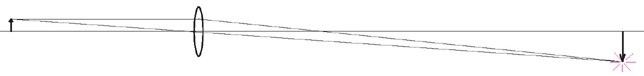
One of AEH’s jobs was to align three LCD images on the screen to 1/10th pixel accuracy and hold them there over long periods of time and over large swings of temperature. The alignment was performed with adjustable fold mirrors to control the Tx, Ty and Rz degrees of freedom of each image. A simple Ivory-in- Excel analysis told us it required a stroke of 17 mr. and a resolution of 0.00026 mr. on each of the fold mirrors.
AEH
had some other resources to bring to the table as well. We were able to
adapt AEH’s patented set-n-forget actuator technology (Intended
for JWST) to the design and manufacture of the mirror mounts. There was a
bit of a breathless interval, however, because AEH could not measure the
sub-microradian resolution. The test was to install the mounts and turn
on the projector. The system worked wonderfully, which verified the
precision of the mirror mounts and the Ivory
analysis.
Here’s to taking care of three images!
Well, that was then and now is NOW.
The great September 1/4 off sale
of AEH/Ivory 3.0 Optomechanical Modeling
Tools has only a few more days to run! Reserve your copy
today.
Optomechanical engineering isn’t always big stuff: hyperspectral sensors; ISR systems; image trackers; boresight control; etc. There’s a lot of fun in the small stuff too.
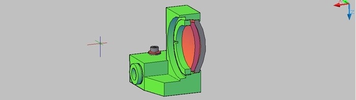
For instance, how can you verify that an ultra-light mirror will be 1/8th wave or better when used in space?
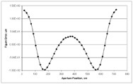
How do you fix a lens assembly product when a large fraction of them fail the MTF test?
How do you drive a lens 10 mm with only 300 nm of runout?
A wag might declare, “It’s all in the
wrists,” but there’s a whole lot more “fun” than that
implies! The Devil is often in the little details.
Yes, AEH does big stuff, we enjoy the small stuff and we make house-calls too.
Whatever helps you!
I’ll be looking for all of you in San
Diego in a few days!
If engineering can be said to have a “purpose” it might be “to survey the available design spaces and guide the design process to avoid future failures.”
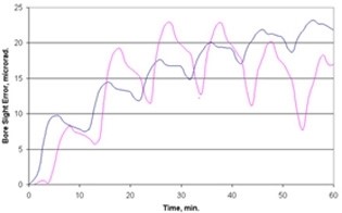
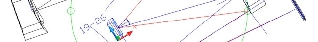
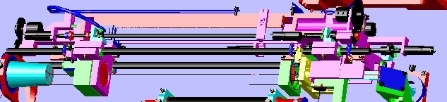
An especially tricky aspect of optomechanical engineering is avoiding unacceptable boresight errors among instruments during thermal transients.
One example is a target designator that was required to operate on a 50% duty cycle with a maximum on-time of five minutes. The boresight was important because the laser and the imager operated in different bands so the operator would not be able to “see” the laser spot in the FOV. The boresight error was required to be less than 15 microradians over one hour of operation. As shown in the figures the maximum boresight error was predicted to be 12 microradians after about 54 minutes (blue is the laser and pink is the imager).
In order to achieve acceptable stability it had
been necessary to add some bracing between the laser beam expander and the
imager’s primary mirror. Adjustments in the position of the laser had
also been necessary. These changes were made early enough in the design
process to avoid a major disruption of the program.
AEH/Ivory Optomechanical Modeling Tools
provided the critical link required to assure the system’s optical performance.
Baltimore was glorious and I had a great group of students. But it’s good
to be home!
You more astute readers have made a good point about my call for completeness and congruence in the modeling data for Nastran optomechanical models: These properties are a necessary condition but, alas, not sufficient.
The goal is to achieve computational zeros in the sums of a few dozen terms of a finite element model that may itself contain a few million terms. But “computational zero” is a relative, not an absolute, term. The engineer needs to demonstrate that the actual value of the computational zeros are small enough to be ignored. Rigid body checks alone can’t do that.
And no technology is more sensitive to this issue than optics. For instance:
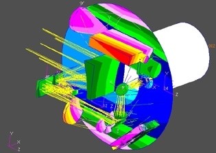
AEH was called to verify the predicted magnitude of dynamic jitter in a spectral imaging system. AEH assembled an all-up meshed solid finite element Nastran model of the system, put the optical prescription through the AEH/Ivory Optomechanical Modeling Tools to generate the complete and congruent data that control the motions of the image on the detector and ran the rigid body checks. Everything so far seemed reasonable.
Then AEH ran three-axis static gravity
checks. Considering the frequencies, displacements and accelerations the
instrument would see AEH judged that the computational zeros, which
dominated the rigid body checks, were two orders of magnitude too large
compared to the static gravity checks. Correcting this required three
more significant figures in the optomechanical modeling data (both the geometry
and the coefficients) for sufficient precision in the dynamic jitter analysis.
Fortunately, the software also produces both geometric and coefficient data
with eighteen significant figures. AEH was able to edit the additional
significant figures into the Nastran database. Finally, AEH ran the
frequency response spectrum. The image jitter proved to be safely within
the system’s specified maximum.
But, the engineer had to take the critical steps to demonstrate sufficient
precision in the optomechanical modeling data.
AEH offers completeness, congruence and
precisionin those critical optomechanical analyses.
Well, the March Hare is here, “I’m late, I’m late, I’m late!”
And as Lewis Carol further wrote, “The time has come….”
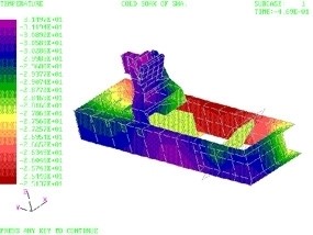
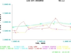
Let me return to the subject of thermal problems in optical systems. I mentioned that I often “linearize” the radiation heat transfer problem. That appeared to confuse some of you so let me explain my position.
I have found that the stability and precision of linear heat transfer solutions uniquely support the precision demanded by high-performance optical instruments. This is especially true during the design phase when mechanical features need to be traded against each other on the basis of their support for the optical image’s quality and stability requirements. My experience has been that this technique captures the physics of the optomechanical problem better than the alternatives.
That was true for the example I gave, the LACE
spacecraft’s UVPI instrument (above), that made the cover of Aviation Week’s
75th anniversary issue. The optical sensor head and both electronics
assemblies (a power supply and the signal processor) were modeled in a linear
heat transfer code.
I kick around this issue (and a number of others) in my class,
“Optomechanical Analysis.” I’ve agreed to present the class in
Baltimore on May 2nd at SPIE’s Defense Security + Sensing Symposium. If
you missed it in San Francisco here’s another opportunity:
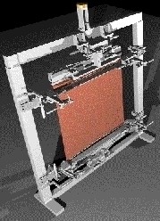
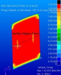
AEH tested, with a client, the ability of metal foils and polymer films to form
membranes with optically useful surfaces such as cylindrical conic sections
(SPIE: 5494-50, 2004). AEH subsequently explored the concept using
non-linear structural solution sequences in MSC/Nastran.
AEH’s study identifies trade-offs among the material properties, dimensional properties, initial conditions and loading. It also provides the optomechanical engineer design tools to minimize the surface figure errors in real, non-idealized, clear apertures. For instance, compensate for defects in the membrane such as non-uniform thickness, variable properties and non-planar initial membrane shapes.
AEH: Cutting-edge engineering for cutting-edge systems.
That is a question I’ve asked my students ever since I started teaching a class on optomechanical tolerancing of instruments, ca. 1990. It’s amazing, the answers I’ve gotten.
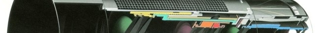
It recurred again recently with a client who had a contract to produce a number of ultra-wide field imaging instruments. The lens was composed of 19 glass elements arranged in nine singlets, four cemented doublets and two cemented triplets. The optical prescription was supplied by their customer as were the allowable alignment tolerances: ±0.005 mm in Tx, Ty and Tz and 20 arc-sec in Rx and Ry.
First, we had to establish the accuracy of their in-house fabrication processes. Getting the crib-notes out of the technicians was real sport. Then we had to find out the accuracy of their suppliers. The latter is usually much more problematic since you don’t really find out anything until you try to negotiate a contract (or, worst-case, only when the parts are delivered). Finally, we had to incorporate alignment mechanisms to make up the deficits, whatever we thought they may be.
You can put it all in a spreadsheet and have great fun with it!
Also back in the ’90s, I was asked by one of the shakers-‘n’-movers in the
optical industry if I would publish a summary of the state-of-the-art of
achievable manufacturing accuracy for the various manufacturing
processes. It would be a great boon to the industry, he said, and indeed
it would. Unfortunately, manufacturing accuracy is not a fixed quantity.
Not only does it vary over time but also with geography, supplier and price
(not to mention attitude). And the variation with each of these is not
always favorable.
In the above example one of my client’s suppliers (actually, their preferred
machine shop) refused to adopt innovative techniques that could provide the
required accuracy, presumably because they had committed to a price before they
knew what was to be demanded of them. Or maybe they didn’t have the
confidence in the precision of their machine tools that I expected. Or
maybe they had too much work and this would disrupt their shop practices.
Who knows?
So, back to the spreadsheet and more fun! Thumb the yellow pages and
buyers’ guides. Explore changes to the construction materials.
Re-tolerance the optics? Call the customer? In some ways good
engineering resembles good accounting; keep pushing the numbers around until
you find a workable combination.
That’s engineering, and one more amazing
answer to that question.