Optomechanics – SOLVED: Elastic Theory’s Differential Equations for the Tensile Stresses in Glass Lenses Mounted in Threaded Metal Rings

Colleagues:

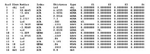
AEH has solved elastic theory’s differential equations for the tensile stresses in glass lenses mounted in threaded metal rings, and it’s good news.

Paul Yoder had originally proposed Delgado and Hallinan’s 1975 solution (Opt. Eng. 14) but their solution gave very high tensile stresses in the lenses, high enough that virtually all such lenses should have fractured.  None of my ring mounted glass lenses had ever suffered that fate.  I surveyed a number of my colleagues and none of them recalled a ring mounted glass lens fracture.

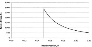
Delgado and Hallinan’s work was flawed.  To correct their flaw would require a new solution to the equations of elasticity that honored the appropriate contact geometry.  AEH finally made it happen and the result is surprisingly simple,

s = p(1-2u)/b,

where s is the peak tensile stress, p is the linear ring load, b is the radius of the contact ring and u is the Poisson’s ratio of the glass.  This stress is three-to-four orders of magnitude lower than that predicted by Delgado and Hallinan.

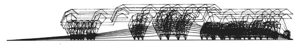
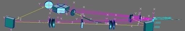
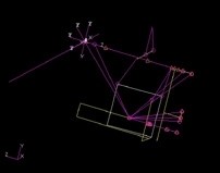
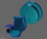
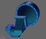
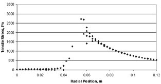
Using Nastran AEH was also able to verify the general shape of the stress distribution in spite of Nastran’s notorious difficulty at the point of load application.


Closed-form solution       >>>         Nastran solution

To learn more you have choices:  Either download AEH’s peer reviewed paper from SPIE [Optical Engineering 57(5), 055105] or go through the gory details with me in my tutorial,

“Optomechanical Analysis,”
SPIE’s Optics and Photonics Symposium in San Diego
8:30 AM to 5:00 PM on the 21st of August.Cheers!

Al H.
6-6-18

Optomechanics – Ivory > Nastran > Excel

Colleagues:

I have always found Excel to be one of the best optomechanical analysis tools. 

AEH has recently enhanced the Ivory3 Optomechanical Modeling Tools to make Nastran and Excel even more powerful for the optomechanical engineer.

It’s not that Nastran doesn’t do its job, but it’s only a finite element code.  For optical systems the engineer needs more methods and tools to interpret Nastran’s results opticallyIvory3 unleashes the power of Nastran into Excel to analyze optomechanical design issues:

Ivory3————————— into –>Nastran———- into —>Excel ——————-|

Optical prescription data    >   opto-structural model   >     LOS error contributors

In this example Ivory3 puts the image registration errors (ie. line-of-sight) into Nastran’s output file, both the net effect and the element-by-element effects, which may be cumulatively summed and plotted in Excel for the engineer’s assessment.  Obviously elements 1, 5 and 11 are the big drivers in this LOS error problem.

When you need to stabilize your image AEH has the tools! Al H.
3-8-18

Optomechanics – Using CodeV Prescription in Ivory and Jade to Find Structural and Thermal Weaknesses

Colleagues:

I’ve been known to lecture my students and colleagues on the need to keep their tools sharp.  Some time ago AEH was invited to a design review as an observer and since I had no direct participation I sat at the back of the room, behind John, the systems engineer who was controlling the projector.  The technical sessions went well but about half-way through the schedule and budget sessions he suddenly blackened the screen and turned on the overhead lights.  He slowly turned and surveyed those of us sitting behind him.  His gaze settled on me!  “What, John?” I asked.  He stared at my hands which were holding my pen knife and its sharpening steel.  “Just keeping my tools sharp,” I declared sheepishly.

One of AEH’s sharpest tools, other than a pen knife, is Ivory’s Optomechanical Modeling Tools.  It’s been under continuous development incorporating many of my personal insights working as a mechanical engineer in the optics industry.  I recently put together an updated version and released it to all users of Version 3.  That’s another way I keep AEH’s tools sharp (and protect AEH’s Ivory subscribers, too).  Ivory is AEH’s prime tool for engineering thermally and structurally reliable optical systems.  It’s designed to work in both Excel and Nastran and its application early in the design process prevents much embarrassment and saves many labor-hours from preventable failures that may occur later in qualification tests and service.

Somewhat more recently AEH was invited to participate in a “Tiger-Team” review of a sub-contractor.  The initial issue was broken glass.  The first thing I did was get a copy of the physical optical prescription (CodeV) and read it into Ivory (for the structure) and Jade (for the broken glass).  I could then quantitatively infer where the principal structural and thermal weaknesses might be.  With that insight I was able to form an independent assessment of the completeness of the design team’s engineering effort, which undergirded my report to the prime contractor.

I hope to see all of you at SPIE’s Optics+Photonics in San Diego come August.  I’ll be teaching (Optomechanical Analysis), chairing (The Optomechanical Engineering Technical Group and Optomechanics 2017), presenting and publishing (on a new diffraction grating capability in Ivory) and begin planning our next SPIE Conference (Optomechanics 2019). 

That also keeps AEH’s tools sharp. 

Hasta luego, caiman.

Al H.
6-5-17

Optomechanics – Voilà. Ivory Analysis Produces Simple Fix

Colleagues:

Brutus to Cassius in Julius Caesar:
“There is a tide in the affairs of men which taken at the flood leads on to fortune.  Omitted, all the voyage of their life is bound in shallows and in miseries.”

A product development project might be considered one of “the affairs of men” to which the Bard was alluding.  My readers, however, should note that it was not “the affairs of men” that was Shakespear’s subject.  Rather, it was “a tide” that Brutus’ declaration (and in fact the whole resulting drama) were about.  Shakespear’s prescient observation has outlived him, at 400 years on the 23rd of April, for good reasons.

AEH guided a re-design effort, the goal of which was to markedly reduce the image jitter due to a random vibration excitation.  The client’s analysts had assumed that “structural” damping was uniformly distributed through the system and had some difficulty simulating problems experienced during service.  Fortunately, there was some accelerometer response data from earlier vibration tests and AEH was able to modify the distribution of damping in their Nastran model to better replicate that earlier data. 

AEH added the Optomechanical Constraint Equations (via Ivory) and “Viola,” the model was now able to reproduce the image jitter observed during service as well.  Using the OCE to parse the Nastran displacement vector identified the major contributors and a simple brace was added to the design to stabilize the image.

None of this was planned.  AEH happened to be on-site and overhear a conversation at the coffee pot.  A tide in the affairs of men was forming.  AEH, with Ivory, was ready.  As a wag might say, “Use it or lose it!”

Rejoice with me at William Shakespear’s 400th birthday!

Al H.
4-19-16

Optomechanics – Simulation vs Analysis

Colleagues:

Recent events have caused me to contemplate distinctions between simulation, on one hand, and analysis, on the other.

AEH was asked to determine the root-causes of a thermal shift in the back focal length of a lithographic lens.  The optical design couldn’t predict it. 

The optical, structural and thermal physics were modeled (we call it “Unified”) in a single code, MSC/Nastran.  The deviations from the actual physics (including simplifications) were noted and quantified.  Check-out results were validated against CodeV to prove their optical rigor.  The analytical results agreed well with experimental data.  Their agreement was limited by the mesh in the finite element model, which is typical in optomechanical problems, and it had been noted among the deviations.  The sources of the thermal shift became obvious in reviewing the output data.  These observables-in-the-data are called “diagnostic vectors.”

AEH calls this approach “Unified Analysis” because it keeps all the data together in a unified database, which is often one printable output file.

If your methods aren’t initially validated, if you haven’t been able to quantify the deviations between your methodology and your sciences and if you cannot trace backward from the “effect” to the “cause” then you’ll probably not recognize the diagnostic vectors, nor be able to identify the sources of problems and formulate solutions.

In the age of eye-candy simulations these practical steps often get lost.  Visuals are good but it’s the numbers, including how they’re derived and how they’re used, that counts.  That’s analysis.

When the numbers are important AEH will be there to help you.

Oh my!  School has started!  Good Luck to all the children.

Al H.
8-24-15

Optomechanics – Save your Budget: Identify Problems Early

Colleagues:

How does a mechanical engineer identify problems early?  He or she runs estimates and analyses, maybe solving two or three degree of freedom (DOF) lumped-parameter problems via simultaneous equations in a spreadsheet.  Estimating surface temperatures on the outside of a cast housing comes to mind with simultaneous radiation, convection and conduction needing to be considered. 

But, throw in optical imaging behavior and the number of equations explodes.  The optomechanical engineer deals with not only the structural and thermal equation but also the 49 equations for each optical element’s effect on the system’s image.  For even modest optical systems this swamps the engineer’s conventional methods.  Who’s going to solve a 100+ equation problem in a spreadsheet?

It’s one thing to write about lumped-parameter optomechanical modeling. It’s a whole other thing to actually do it.  The optomechanical engineer needs optomechanical toolsHere’s a “relatively simple” 874 equation (DOF) optical/structural lumped-parameter model:

All of the 784 optics equations were modeled in AEH/Ivory and imported to the MSC/Nastran lumped-structural model (90 equations) for numerical solution.  The Nastran run identified critical thermal alignment challenges, the solution to which enabled a successful telecoms product.  Assembling and running simple lumped-parameter optomechanical models saves budgets, saves schedules and snatches success from the jaws of failure.  That’s engineering.

If you have questions give AEH a call.

I’ll talk more about this in San Diego at SPIE’s Optics+Photonics Symposium, come August.  We’ll have a two-day conference, poster sessions and an evening meeting of the Optomechanical Engineering Technical Group.  It’ll be a great time with technical exhibits, banquets and camaraderie.  I hope to see you all there.

Meanwhile… identify problems early, stay on top and keep your tools sharp!

Al H.
6-10-15

Optomechanics – Prepare for Success Early

Colleagues:

Optics is an art that’s just meant to work… until it doesn’t. 

The optomechanical engineer’s job is to survey the available mechanical design spaces looking for optical problems.  The engineer identifies the problems early, gets on top of them and stays on top all the way through.  MSC Software Corporation recently published a Case Study on this subject.  Here’s the link—

Optomechanics at MSC

Many problems can be anticipated and avoided by using relatively simple, lumped-parameter models in the beginning of a project.  If the project waits until the distributed properties are well defined it may be too late and the budget and schedule considerations may even shut the project down.  Optomechanical analysis is at least an order of magnitude trickier than the individual disciplines alone.  So the engineer has to have tools, and that means being able to couple the structure to the optical behavior in a single code.  AEH uses MSC/Nastran and AEH/Ivory.

Here are two examples, one a success the other a failure.  Both were gimbal-stabilized telescopes of roughly the same size:

The failure was a project that would not let the lumped parameter LOS model be run in the beginning but insisted that the analysis model be prepared from the finished engineering drawings.  The full-up analysis showed an unstable LOS.  Redesigned solutions were possible but costly. This project was cancelled. 

The successful project was able to demonstrate sufficient margin of safety with the lumped parameter LOS model that a full-up optomechanical model wasn’t needed.  The structural engineers could concentrate on strength and safety.  This project was fielded. 

Neither outcome was intuitive or obvious at the projects’ beginnings but their results couldn’t have been more stark.

Powerful tools, simple models, early in the project:  The eye-candy may be poor but the numbers can save the engineer’s buttons.

Spring is lovely in Pasadena.  I hope you’re enjoying it as much as I am.

Al H.
5-14-15

Optomechanics – Ivory and Cluster Lenses for Panoramas

Colleagues:

I’ve shared with you the tale of the errant window in a vacuum chamber where the issue with the instrument under test was less a change of the effective focal length than a change in the back focal length.  Well, here’s another tale along a similar vein.

It concerns a lens for cameras used in clusters to make large panoramic images stitched together from the smaller individual images.  The lens had to be entirely passive, no adjusting mechanisms were allowed.  They came up with an ingenious combination of glasses that would produce the required image quality as well as exactly balance out the thermal expansion of an aluminum alloy structure so as to stabilize the effective focal length over a broad range of temperatures.  In service tests the image size was perfect for stitching but the image was out of focus at the extreme temperatures.  They had assumed that the second principal plane (and therefore the back focal length) was stationary.

The situation becomes evident when the prescription is put into Ivory.  Importing Ivory’s output file into a spreadsheet permits calculation of both the focus registration sensitivity, Tzi/C°, and the image size sensitivity, DM/Mi-C°. 

Control of two dependent degrees of freedom, image size and image focus, requires two independent variables.  Only the properties of the aluminum alloy in the housing were available so only one of the variables could be “zeroed.”  The back focal length was left to float with the focus registration, TZi/C.  Rummor has it that they finally added a focus mechanism.

The Ivory Optomechanical Modeling Tools provides the engineer access to these behaviors of optical images, avoiding much embarrassment.

The all new Ivory 3.0 is now available with annotated project files, diffraction gratings, Unified Nastran modeling and much, much more.

And just in time for Valentine’s day!

Al H.
2-5-15

Optomechanics – Early Adoption Matters

Colleagues:

At AEH we study closely the ways things fail.

It is often said that an engineer’s job is to make things work.  Well, that’s nice.  Tinkerers can do that too.  What’s really required from engineers is to make things work every time.  That’s a little different discipline. 

So, as engineers AEH studies how things fail in order to better know how to prevent bad things from happening:

In optical systems, virtually all “optical” failures result from some defect in the mechanical implementation.  These failures are never corrected by changing the optical prescription.  Well, almost never:  There was the Hubbell primary mirror fix.

Optomechanical problems are best spotted early, while the design resources (size, shape, mass, arrangement, interfaces, etc.) are malleable.  Those resources can quickly become depleted, even unavailable, as they are claimed by other interests:  bearings, servos, electronics, cryogenics, subcontractors, etc.

Early detection requires special tools for the optomechanical engineer.  To assess optomechanical problems the optics and mechanics must be coupled by the engineer, hopefully from the first publication of the prescription, perhaps during the proposal effort even. 

The results of this early optomechanical coupling may only be estimates, but they’re essential.  They give the engineer who uses them a sense of how to guide the design to his desired…, no, to his required destination: 

Spot-on performance with a trouble-free service life.

Early assessment of optomechanical problems is one way we help our clients.  AEH has the tools:  longhand, ten-key, spreadsheet and Nastran. We’ve got all that plus Ivory, Ebony and Jade to interpret the optomechanics for you.

Of course, we can often help after problems materialize and the corrective options have become more restricted.

Joy to all for the Autumn season.  It has arrived!

Al H.
10-6-14

Optomechanics – How to Design with Ivory

Colleagues:

When performance is crucial the engineer uses tools to assure it.  Let me show you:

Say, we need a hyperspectral design with a 60 cm entrance pupil and stabilized to less than 15 ur, rms, LOS error in object-space.  We have the physical prescription.  How to get started?

The first thing I do is run the physical prescription data through AEH/Ivory Optomechanical Modeling Tools and import them into MSC/Patran-Nastran to start a system model (1).  The pink lines represent the optics and the yellow lines are structural bar elements with lumped masses. 

It’s a crummy “visual” but a very important first step.  I validate the model with rigid-body checks.  Then I run the model through random vibration adjusting the properties of the bar elements (areas, inertias, materials, etc.) until AEH/Ivory-in-Nastran satisfies the LOS performance requirement (12.3 ur, rms, in this case) with a reasonable combination of properties.

(1) 12.3 ur, rms
(2) 12.8 ur, rms
(3) 11.9 ur,rms
(4) 12.7 ur, rms

Next I incorporate solid models of the optical elements and replace the simple bars with more complicated beam elements (rectangular and circular tubes, some tapered) and optimize their wall thicknesses to maintain the AEH/Ivory-in-Nastran LOS performance (2).  I now have an estimate of a housing geometry (masses, dimensions, thicknesses) that will meet the LOS performance. 

The CAD engineer has decided on a three-piece housing design; an objective, a compound elbow and a detector.  The first section we develop is the compound elbow that holds the grating.  The CAD engineer makes a model which I import into the system model.  When we have an elbow design that maintains the AEH/Ivory-in-Nastran LOS performance in the system model, (3), we move ahead.

We design the objective and the detector sections next, import them, one at a time, into the system model.  We run the model through random vibration adjusting properties to maintain the AEH/Ivory-in-Nastran LOS performance before proceeding.  Finally, (4), we have developed a three-piece optical housing design through an iterative engineering process that supports the required LOS stability.

That’s optomechanical engineering with tools.  No surprises.  No excitement.  Just getting where we need to go, working from the optical prescription.

Now, to play a little…

Oh!  Joyous Summertime.

Al H.
7-7-14