Putting EO gear on Navy aircraft is a special sort of challenge, particularly
if it’s external stores. Not only does it have to pass the normal shock
and vibration tests, it has to pass the rigors of catapult launches and
arrested landings.
AEH was on the team that put active IR countermeasures into NavAir service.
The big challenge was the survival of the IR source which, until that time,
existed only in the research lab. We had to establish its fragility
threshold (by testing) and then design its installation to survive the
cats-n-traps of carrier service. The solution turned out to be custom,
AEH-designed, shock isolators and snubbers, one of AEH’s applications of the
principles of optical flexures. It was a six-degree-of-freedom
“kinematics” problem with about a dozen degrees-of-freedom in the
kinetic (design) solution, and non-linear at that. Great fun!
There aren’t always “canned” tools that the engineer can apply. This case required writing an interactive numerical integration routine that could be iterated quickly to explore the effects of the numerous design variables. Spreadsheet approaches were too cumbersome so source-code was written and compiled. The engineer could quickly modify the design variables and/or computational parameters and rerun the problem. This enabled a thorough survey of the design space, demonstrations of numerical stability and, ultimately, the determination of the most favorable design configuration.
It’s always good to have a source-code compiler around. It also helps to keep your other tools sharp.
AEH: Finding engineered solutions.
Spring must be coming. The apple trees are in full bloom!
A while ago I got a call from a sponsor who wanted me to go to a design review in Texas on very short notice. On arrival I found my name was on the attendance list but no one knew why. There were a lot of peculiar looks around the registration desk.
I took a seat at the back of the auditorium and quietly made notes. At coffee break the manager who was funding the subcontract being reviewed came back to introduced himself. He tried to “talk shop” but I had very little I could say as I’d not been briefed by my sponsor. I was learning as I listened.
It was mid-morning of the second day that I discovered why I was there. They had made the hottest doubled-YAG laser I’d seen, but it was unstable. The laboratory system worked fine but the flight system lost power whenever a door in the room was closed. Hmmm.
Well, at lunch break I chatted with the laser scientists, who were bewildered by the problem. So I talked to the mechanical engineers and asked them what they did for the flight system that was different from the laboratory system. They said, uniformly, “Nothing.”
After lunch, back in the design review, I
discovered what “nothing” was. The mechanical engineers had
been directed to put the resonant cavity on a “kinematic mount,”
which they did. It worked great. In the flight environment however
the “kinematic mount” would fly apart so they bolted it together for
flight. The “stiction” in the “bolted kinematic
mount” prevented the cavity’s return to its original geometry after a
disturbances such as the closing of doors.
In my report to my sponsor I suggested that a simple redesign to replace the
failed “kinematic mount” with a “kinetic mount” (i.e.,
flexures) would probably fix the problem. But it was too
late. Within a short time the whole project was cancelled.
A warning to optomechanical engineers: “Kinematic mount” is
just a figure of speech. “Kinematics” is defined as “the
study of motion without regard to forces or masses.”
“Kinetics” is the study of motions of masses under the influence of
forces. When asked for a “kinematic” mechanism we should
request the allowable motions. We can usually work out the
“kinetics” from there. If you cannot find out the allowable
motions be very, very careful.
I had a good class of students for my tutorial on Thursday at SPIE’s Defense,
Security and Sensing Symposium.
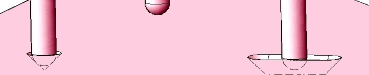
Well, with Summer around the corner this may be my last chance to tickle your consciousness before the lazy days set in. My subject this time is broken flexures, specifically broken double cantilever blade flexures of the sort shown:
I have long been reluctant to use this type of flexure because the double cantilever beam, being restrained on both ends, is not well described by linear elastic structural theory. Rather than study the problem I’ve just avoided it, until now. The difference between now and then is that a friend has some broken double cantilever blade flexures now and has sought my counsel. Well, one thing leads to another and here I am: With a friend who has broken flexures. Way back then broken double cantilever blade flexures were less personal, just conjectural. I was able to avoid the whole issue. But, now is now so here I go.
The “problem” with the double cantilever beam, and the flexures that rely on its mechanics, is they don’t fit “well” into the small displacement linear elastic theory that is usually used to analyze them for strength and stiffness. As I will show it all depends upon what you may call a “small displacement.”
As you deflect the double cantilever beam flexure by applying a load in the center, the center will deflect and the length of the beam will increase, at first slowly and then faster and faster. This increase in length creates axial forces and tensile stresses in the beam (flexure). This increase in length is a second order effect in the differential equations and therefore ignored by the small displacement linear elastic theory. The Euler-Bernouli beam theory agrees with the finite element method that these tensile forces and stresses do not exist. But intuitively they have to be there. How severe is this discrepancy?
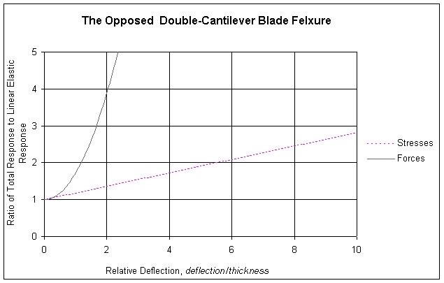
I take as my starting point some earlier work (Hatheway, SPIE, 3132-19, 1997) on the radius of curvature of the locus of the end point of a cantilever beam. This permits the calculation of the foreshortening of a free cantilever beam, which would be equal to, and opposite in sense to, the stretching in a constrained cantilever beam. With this information I was able to estimate the forces and stresses attributable to the stretching of the beam (flexure). These need to be added to the Euler-Bernouli results. They are shown in the following chart, the vertical axis of which presents a ratio which is the sum of the Euler-Bernouli bending effect and the non-linear stretching effect divided by the Euler-Bernouli bending effect alone. The magnitude of the ratio is shown for both stress effects and force resultant effects. The horizontal axis is the deflection of the flexure as a multiple of the thickness of the flexure’s blade.
As you may observe the stresses and forces agree
reasonably well with the linear elastic stresses and forces when the
deflections (and therefore the Relative Deflections) are very small,
approaching zero. When the deflection approaches the thickness of the
blade (Relative Deflection equal to 1.0) the state of stress is about 18%
higher (Ratio=1.18) than the linear elastic stresses alone and the reaction
force is about 72% higher (Ratio=1.72) than the linear elastic bending load
alone. From there the values increase, the force values quite rapidly.
Thus, for a given deflection the designer may estimate the total force and the
total tensile stress in the flexure: First, from the required deflection,
calculate the linear elastic values for stress and force from conventional beam
theory (or a finite element model). Then multiply these by the factors
from the chart. These are still “small displacement” results, but
“nonlinear” as you can see, incorporating only one higher order or
higher degree term in the solution. (A caution: It is not at all
clear that these are valid all the way out to a Relative Deflection of
10. Other higher order terms surely will contribute somewhere in this
range.) One open question is then, “Just how small is the small
displacement domain?” One answer might be based upon desired
accuracy. Another might just seek to satisfy some required Factor of
Safety. Obviously, if the displacements are small enough one needn’t
worry about non-linear effects (Or any effects at all, a wag might point out!).
Well, that’s kinda’ what I’ve been up to this Springtime. And now, with
the weather warming up and a fresh tube of sun-block I’m ready to let you
go.
But first — I’ve been invited to address the Optical Society of
Southern California (OSSC) at their dinner meeting on June 23rd. My
subject will be “Applying the Arts of Structural Engineering to
Optics.” It is an open meeting, anyone may attend, but you must make
reservations if you’ll be there for dinner. I promise to be more
entertaining than this dry missive.
The meeting will be at Luminaria’s Restaurant in Monterey Park, near the
intersection of Interstate 10 and Interstate 710. I expect to be
challenged on the relevance of the “linear small displacement
domain,” other charming topics and I look forward to a vigorous
discussion. Hope to see you all there.