Optomechanics – Tensile Strength of Glass

Colleagues:

OK, AEH hit you in May you with analyzing the tensile stresses in cemented glass doublets.  Then AEH hit you in June with analyzing the tensile stresses in ring-mounted glass lenses.  And you responded with numerous queries about AEH’s analytical methods… but they were surrounded by a massive silence.

No one asked, “What’s the tensile strength of the glass?”

It’s a characteristic attitude in the optical industry, that the strength of glass is not its problem, “Leave that to the structural engineers.”

Well, surprise!   The structural engineers don’t care either.   Glass, being brittle, is in no-way a structural material.  Structural engineers design with ductile materials like steel and aluminum.  The only brittle material they routinely design with is concrete and they insist that it never see tensile stresses.  That’s why they invented pre-stressed concrete: to eliminate the tensile stresses!

The tensile strength of a glass is determined by its “fracture toughness,” a material property of the glass that can be measured in a test lab and is repeatable.  However, among the silica glasses the values for fracture toughness appears to vary, based on the very limited data available, by factors between 3 and 5, depending upon the specific glass composition.  It makes a big difference which glass is used in high-stress situations.

Ah, just one of the challenges
(and one of the joys!)
of optomechanical engineering.

Al H.
7-2-18

Optomechanics – SOLVED: Elastic Theory’s Differential Equations for the Tensile Stresses in Glass Lenses Mounted in Threaded Metal Rings

Colleagues:

AEH has solved elastic theory’s differential equations for the tensile stresses in glass lenses mounted in threaded metal rings, and it’s good news.

Paul Yoder had originally proposed Delgado and Hallinan’s 1975 solution (Opt. Eng. 14) but their solution gave very high tensile stresses in the lenses, high enough that virtually all such lenses should have fractured.  None of my ring mounted glass lenses had ever suffered that fate.  I surveyed a number of my colleagues and none of them recalled a ring mounted glass lens fracture.

Delgado and Hallinan’s work was flawed.  To correct their flaw would require a new solution to the equations of elasticity that honored the appropriate contact geometry.  AEH finally made it happen and the result is surprisingly simple,

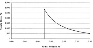
s = p(1-2u)/b,

where s is the peak tensile stress, p is the linear ring load, b is the radius of the contact ring and u is the Poisson’s ratio of the glass.  This stress is three-to-four orders of magnitude lower than that predicted by Delgado and Hallinan.

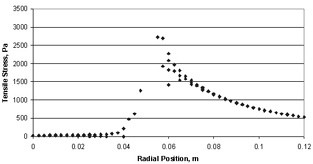
Using Nastran AEH was also able to verify the general shape of the stress distribution in spite of Nastran’s notorious difficulty at the point of load application.


Closed-form solution       >>>         Nastran solution

To learn more you have choices:  Either download AEH’s peer reviewed paper from SPIE [Optical Engineering 57(5), 055105] or go through the gory details with me in my tutorial,

“Optomechanical Analysis,”
SPIE’s Optics and Photonics Symposium in San Diego
8:30 AM to 5:00 PM on the 21st of August.Cheers!

Al H.
6-6-18

Optomechanics – Quick Checks for Stress in Glass

Colleagues:

Well, Ok.  It’s not that AEH hasn’t seen broken glass this past year, it’s just that it hasn’t been AEH’s glass that broke.  Cemented doublets were the principal excitement.  AEH’s research indicates that, for a quick check,

tensile stress in the glass =~ (E1 + E2)/2 x (alpha1 – alpha2) x deltaT

and

shear stress in the adhesive =~ 2/3 x tensile stress in the glass.

If stresses are marginal the engineer may then want to adjust for the edge thicknesses of the lenses and the Poisson’s ratios of their glasses.  The peak shear and tensile stresses occur at or near the edges of the lenses.  The only dimensions that influence the stresses are the edge thicknesses.  Center thickness and diameter have little influence on the stresses at the edges.

  Radial Tension                             Shear                                 Axial Tension

Does it all seem spooky?  Well, I’ll take you through the gory details in my tutorial,

“Optomechanical Analysis,”
August 21st in San Diego at SPIE’s Optics and Photonics Symposium.

And, I’ll toss in, just for you, the latest details on the stresses in ring-mounted glass lenses including a close-form solution and a finite element simulation!

I’ll see you all in San Diego.  Bring your sun-screen. Al H.
5-4-18

Optomechanics – Ivory > Nastran > Excel

Colleagues:

I have always found Excel to be one of the best optomechanical analysis tools. 

AEH has recently enhanced the Ivory3 Optomechanical Modeling Tools to make Nastran and Excel even more powerful for the optomechanical engineer.

It’s not that Nastran doesn’t do its job, but it’s only a finite element code.  For optical systems the engineer needs more methods and tools to interpret Nastran’s results opticallyIvory3 unleashes the power of Nastran into Excel to analyze optomechanical design issues:

Ivory3————————— into –>Nastran———- into —>Excel ——————-|

Optical prescription data    >   opto-structural model   >     LOS error contributors

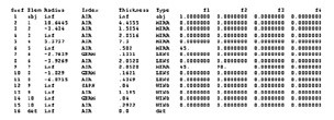
In this example Ivory3 puts the image registration errors (ie. line-of-sight) into Nastran’s output file, both the net effect and the element-by-element effects, which may be cumulatively summed and plotted in Excel for the engineer’s assessment.  Obviously elements 1, 5 and 11 are the big drivers in this LOS error problem.

When you need to stabilize your image AEH has the tools! Al H.
3-8-18

Optomechanics – Secret Sauce

Colleagues:

Optomechanical engineers are a lot like professional chefs.  Each has a “secret sauce.”  Just like chefs we sample and adjust our sauces all the time to be sure they’ll come out consistently good.

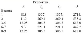
AEH’s secret sauce is selections from W. J. Smith and R. J. Roark blended into K-J. Bathe.  Below I use the optical prescription to determine the optomechanical constraint equations (OCE) between each of its ten optical elements and the image on the detector (pink).  I then estimate the required stiffness properties of the structure between the elements, I define a lumped mass for each of the optical elements and connect them together with the nine beams (yellow) with the (estimated) proper stiffnesses.  I run it for the LOS error:

This initial run is usually off-target but it provides a starting point.  I replace the lumped masses with the actual lenses (from step files) and adjust the stiffness of the beams until I’m in the ballpark of the required LOS error.  Then I guide the design of the CAD structure to have the proper proportions to meet the required LOS error…

Voi-la!

1.3 ur rms . . . LOS . . .  1.4 ur rms
from Proposal    ——————————————————>    to Product.

AEH’s sauce provides the project a continuous and traceable record of the adequacy of the structural stiffness supporting the optical system from the earliest concepts to the final tested product.  AEH’s sauce is a little different every time, just like its culinary counterpart.

Bon appetite!

Al H.
2-7-18

Optomechanics – Recommended Reading

Colleagues:

Joy to all, and thank you for your awesome support of our Optomechanical Engineering 2017 Conference in August.  Just wait ’till you see the program.

Now, back to business.  Fractures in glass optics seem ubiquitous. 

So… the optomechanical engineer has a problem.  He’s nominally responsible for protecting the glass elements in the optical systems he designs.  But there’s very little (if any) information available on the structural properties of the glasses that optical designers specify.  And the guidance for the engineer on using the available data is all-over-the-map, from the incomprehensible to the impossible.  No wonder most engineers use simple “rules-of-thumb.”

That’s where I started, “Keep the tensile stresses under 2,000 psi.”  But then the glass broke anyway!  So I started testing the glass objects to 4,000 psi.  I broke a few in testing but those that went into service are still in service, as far as I know.  I didn’t get to make many, they were too big and heavy.  A colleague who specialized in space-based ISR systems confided to me that he kept the stresses under 500 psi!  That’s when another colleague gave me a copy of “Reconnaissance and Surveillance Window Design Handbook” (AFAL-TR-75-200). 

Voila!  Section 7.3.1 is the perfect introduction for the engineer to “Allowable Stresses in Glass.”  It covers fabrication process controls, slow crack growth through stress corrosion (from moisture) and estimating the service life by integrating the stress corrosion equations for eight glasses.  The Wizard’s green curtain is drawn back disclosing all of his secrets and Dorothy dances down the yellow brick road and back to safety in Kansas.

Every optomechanical engineer needs a copy of that Handbook to help him protect the optical glass that has been entrusted to him by the optical designer.  It guides the design, analysis and fabrication of glass optical elements.  Perhaps the engineer should enter the required structural properties, including the fracture toughness and stress corrosion constants, on the lens drawings (think the yellow brick road).  The Handbook’s drawback is that only eight glasses are treated and some of those have since been re-formulated to remove toxic elements.

The glass suppliers also need copies of the Handbook so they’ll know what the engineer is requesting and, maybe someday, put the information in their glass catalogs and data sheets.

Joy!  Spring is just around the corner.  Ahh… Kansas in Springtime!

Al H.
3-10-17

Optomechanics – Non-Structural Solid Mechanics

Colleagues:

I was in the Boston area recently to teach one of my day-long classes in optomechanics.  It was terrific to meet with an enthusiastic group of engineers.  I introduced them to a number of technical issues that they probably did not encounter in their college or university days.  One of those issues was “non-structural” solid mechanics.

There are aspects of the optomechanical design arts that fall into an academic “chasm” that lies somewhere between structural engineering and mechanical engineering.  Structural engineers study the behavior of “structural materials” that are thought to be safe for civil applications (office buildings, railroad bridges, aircraft).  Mechanical engineers may be introduced to the behavior of structural materials but also must study other topics such as machine design, heat and mass transfer, vibration theory and thermodynamics that are necessary to understand their industrial applications (automobiles, escalators, power generation). 

Optomechanical design often calls upon a variety of “civilly” un-safe materials (glasses and elastomers for instance) that may be incompletely characterized and not well understood or appreciated by either structural engineering (which tends to avoid them) or mechanical engineering (which may be largely unaware of their limitations). 

In my classes I attempt to bridge this chasm by introducing the available science for these non-structural materials.  The “strength” of glass is one topic and the “stiffness” of elastomers is another.  They make an interesting pair in that they both are considered “brittle” materials requiring some knowledge of fracture mechanics while elastomers may also require a large-displacement elastic theory which has never been fully developed.  Fun stuff.

Yes, rubber is a brittle material!

I look forward to seeing you in San Diego at the end of the month… and while you’re there don’t forget to drop by SPIE’s bookstore to peruse my new book, The Optomechanical Constraint Equations:  Theory and Applications.  I wrote it just for you.

See you all there!

Al H.
8-11-16

Optomechanics – Keep Your Tools Sharp

Colleagues:

If spherical surfaces didn’t make pretty good images our optical industry would be entirely different.  As befits a technology that basically works as intended, cliches and rules-of-thumb perform a yeoman’s service.  And they work!  I’m glad that many of you enjoyed my parable about “kinematic” mounts.  Well, that is, they work until they don’t, as in that misunderstanding between the laser physicists and the mechanical engineers.  Thanks for all of your comments.

More recently I’ve been inspired by some of my students to publish the optomechanical influence coefficients of diffraction gratings (i.e., the ratios of a spectrum’s motions to the grating’s motions).  Gratings are often simulated as mirrors.  But the grating’s influence coefficients differ slightly from the mirror’s and there are more of them.  I’ll present my results in Mark Kahn’s conference, “Optical Modeling and Performance Predictions VI,” at SPIE’s meeting in San Diego this August. 

Imaging spectrometers (using gratings of course) are particularly challenging to the optomechanical engineer because the images of both the far-field object and the near-field slit (the spectrum) need to be stabilized simultaneously on the detector plane.  The slit operates as a field stop and the two images behave somewhat (and sometimes importantly) differently.  “Mining” the resulting “data cube” requires close registration between the spectrum and the far-field object’s image.  The grating will work in my Ivory Optomechanical Modeling Tools software.

In San Diego I’ll also present a paper in my own conference, “Optomechanical Engineering 2013.”  This presentation will describe the use of my Jade Optomechanical Modeling Tool.  Jade models the subsurface cracks induced by grinding and polishing.  I use it to engineer, for structural safety, components made of glasses, ceramics and other brittle materials.  As an example I’ll show how I applied Jade to meter-class optical windows for a civilian transport-class aircraft.  The windows have been in service for years.

Engineers develop tools to keep themselves out of trouble.  In the public works domain these have developed into codes and standards that engineers are obligated (by their insurance companies) to follow.  Elsewhere, engineers develop tools for themselves.  In optomechanical engineering there are few rules of thumb to help.  There are, however, a few cliches. 

Summer is coming!  Get out the sunscreen and water skis again!

Keep your tools sharp and your wits even sharper.

Hasta luego, caimán.

Al H.
6-18-13

Optomechanics – The Trap of “Kinematics” vs “Kinetics”

Colleagues:

A while ago I got a call from a sponsor who wanted me to go to a design review in Texas on very short notice.  On arrival I found my name was on the attendance list but no one knew why.  There were a lot of peculiar looks around the registration desk.

I took a seat at the back of the auditorium and quietly made notes.  At coffee break the manager who was funding the subcontract being reviewed came back to introduced himself.  He tried to “talk shop” but I had very little I could say as I’d not been briefed by my sponsor.  I was learning as I listened.

It was mid-morning of the second day that I discovered why I was there.  They had made the hottest doubled-YAG laser I’d seen, but it was unstable.  The laboratory system worked fine but the flight system lost power whenever a door in the room was closed.  Hmmm.

Well, at lunch break I chatted with the laser scientists, who were bewildered by the problem.  So I talked to the mechanical engineers and asked them what they did for the flight system that was different from the laboratory system.  They said, uniformly, “Nothing.”

After lunch, back in the design review, I discovered what “nothing” was.  The mechanical engineers had been directed to put the resonant cavity on a “kinematic mount,” which they did.  It worked great.  In the flight environment however the “kinematic mount” would fly apart so they bolted it together for flight.  The “stiction” in the “bolted kinematic mount” prevented the cavity’s return to its original geometry after a disturbances such as the closing of doors.

In my report to my sponsor I suggested that a simple redesign to replace the failed “kinematic mount” with a “kinetic mount” (i.e., flexures) would probably fix the problem.  But it was too late.   Within a short time the whole project was cancelled.

A warning to optomechanical engineers:  “Kinematic mount” is just a figure of speech.  “Kinematics” is defined as “the study of motion without regard to forces or masses.”  “Kinetics” is the study of motions of masses under the influence of forces.  When asked for a “kinematic” mechanism we should request the allowable motions.  We can usually work out the “kinetics” from there.  If you cannot find out the allowable motions be very, very careful.

I had a good class of students for my tutorial on Thursday at SPIE’s Defense, Security and Sensing Symposium.

Wasn’t Springtime in Baltimore gorgeous? 

Joy to all.

Al H.
5-14-13

Optomechanics – Thermal Problems in Optical Systems

Dear Colleagues:

Let me return to the subject of thermal problems in optical systems.  I mentioned that I often “linearize” the radiation heat transfer problem.  That appeared to confuse some of you so let me explain my position.

I have found that the stability and precision of linear heat transfer solutions uniquely support the precision demanded by high-performance optical instruments.  This is especially true during the design phase when mechanical features need to be traded against each other on the basis of their support for the optical image’s quality and stability requirements.  My experience has been that this technique captures the physics of the optomechanical problem better than the alternatives.

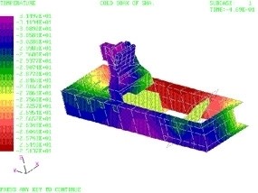
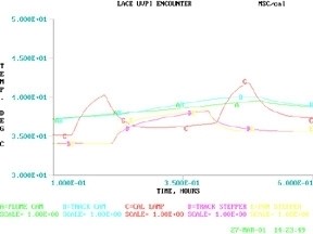
That was true for the example I gave, the LACE spacecraft’s UVPI instrument (above), that made the cover of Aviation Week’s 75th anniversary issue.  The optical sensor head and both electronics assemblies (a power supply and the signal processor) were modeled in a linear heat transfer code. 

I kick around this issue (and a number of others) in my class, “Optomechanical Analysis.”  I’ve agreed to present the class in Baltimore on May 2nd at SPIE’s Defense Security + Sensing Symposium.  If you missed it in San Francisco here’s another opportunity:

http://spie.org/app/program/index.cfm?fuseaction=COURSE&export_id=x12502&ID=x6771&redir=x6771.xml&course_id=E2019181&event_id=1042005&programtrack_id=634

Spring is here!  Can you believe it?

Al H.
3-19-13