Optomechanics* – Jade Brittle Fracture Analysis Tool

*A note from Teale Hatheway: As I pored over Dad’s emails to organize and archive AEH’s Optomechanics Newsletter, I came across this gem which, dated 7-18-18, was never shared. I also discovered an abundance of conversations sparked by these communications. It’s no wonder Dad enjoyed his work well past “retirement age”: your camaraderie combined with his intellectual pursuits gave him great joy. He would’ve called it “sport.” With well over 100 Optomechanics Newsletters published since 2006, the experience of compiling these brought me renewed clarity on Al’s life work. From AEH product announcements, to carefully worded client stories, to occasionally revealing his trade secrets, I hope you will continue to enjoy his wit and his wisdom here… So here we go! The last Optomechanics. I sure hope he finished editing it. Enjoy!

———–

Colleagues:

Put fracture mechanics to work for you!

Fracture mechanics says that glass is sensitive to static stress corrosion fatigue effects.  Glass parts have finite fatigue lives when operated in a normal moist environment.  If the fatigue life, T, is defined as the time to fracture under the conditions of service, that life may be calculated from

noting that KIi is the initial stress intensity, KI is the instantaneous stress intensity, KIc is the fracture toughness, v is the instantaneous crack growth rate and the local stress, s, is time-variable and it is inside the integral.

AEH recruits our Jade Brittle Fracture Analysis Tool, to perform the numerical integration and determine T, the fatigue life.  For Jade it’s a piece of cake!

For instance, take this thermal-structural stress transient for an aircraft’s window requiring 10,000 flight hours of service life:

 FULL STRESS CYCLES AT FRACTURE= 3563
TIME TO FRACTURE= 44896587.75 
SECONDS= 12471.274375 HOURS
CRITICAL INITIAL TENSILE STRESS= 55002270.5466022
INITIAL CRACK DEPTH= .000149 

If the engineer applies a reasonable factor of safety, say 1.5, to the critical initial tensile stress (the ultimate load) it will provide a proof test load (82.5 MPa in this case) that will assure the safety of the window throughout its service life.

There’s no way to get there with closed-form solutions and it’s way too big for an Excel spreadsheet.  Jade goes through the complete calculation in just seconds, allowing the engineer to try various combinations of design variables to optimize a safe concept.

Jade Brittle Fracture Analysis Tool
Now available from AEH.

Al H.
7-18-18

Optomechanics – Tensile Strength of Glass

Colleagues:

OK, AEH hit you in May you with analyzing the tensile stresses in cemented glass doublets.  Then AEH hit you in June with analyzing the tensile stresses in ring-mounted glass lenses.  And you responded with numerous queries about AEH’s analytical methods… but they were surrounded by a massive silence.

No one asked, “What’s the tensile strength of the glass?”

It’s a characteristic attitude in the optical industry, that the strength of glass is not its problem, “Leave that to the structural engineers.”

Well, surprise!   The structural engineers don’t care either.   Glass, being brittle, is in no-way a structural material.  Structural engineers design with ductile materials like steel and aluminum.  The only brittle material they routinely design with is concrete and they insist that it never see tensile stresses.  That’s why they invented pre-stressed concrete: to eliminate the tensile stresses!

The tensile strength of a glass is determined by its “fracture toughness,” a material property of the glass that can be measured in a test lab and is repeatable.  However, among the silica glasses the values for fracture toughness appears to vary, based on the very limited data available, by factors between 3 and 5, depending upon the specific glass composition.  It makes a big difference which glass is used in high-stress situations.

Ah, just one of the challenges
(and one of the joys!)
of optomechanical engineering.

Al H.
7-2-18

Optomechanics – SOLVED: Elastic Theory’s Differential Equations for the Tensile Stresses in Glass Lenses Mounted in Threaded Metal Rings

Colleagues:

AEH has solved elastic theory’s differential equations for the tensile stresses in glass lenses mounted in threaded metal rings, and it’s good news.

Paul Yoder had originally proposed Delgado and Hallinan’s 1975 solution (Opt. Eng. 14) but their solution gave very high tensile stresses in the lenses, high enough that virtually all such lenses should have fractured.  None of my ring mounted glass lenses had ever suffered that fate.  I surveyed a number of my colleagues and none of them recalled a ring mounted glass lens fracture.

Delgado and Hallinan’s work was flawed.  To correct their flaw would require a new solution to the equations of elasticity that honored the appropriate contact geometry.  AEH finally made it happen and the result is surprisingly simple,

s = p(1-2u)/b,

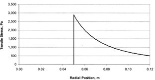
where s is the peak tensile stress, p is the linear ring load, b is the radius of the contact ring and u is the Poisson’s ratio of the glass.  This stress is three-to-four orders of magnitude lower than that predicted by Delgado and Hallinan.

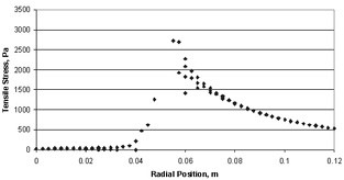
Using Nastran AEH was also able to verify the general shape of the stress distribution in spite of Nastran’s notorious difficulty at the point of load application.


Closed-form solution       >>>         Nastran solution

To learn more you have choices:  Either download AEH’s peer reviewed paper from SPIE [Optical Engineering 57(5), 055105] or go through the gory details with me in my tutorial,

“Optomechanical Analysis,”
SPIE’s Optics and Photonics Symposium in San Diego
8:30 AM to 5:00 PM on the 21st of August.Cheers!

Al H.
6-6-18

Optomechanics – Quick Checks for Stress in Glass

Colleagues:

Well, Ok.  It’s not that AEH hasn’t seen broken glass this past year, it’s just that it hasn’t been AEH’s glass that broke.  Cemented doublets were the principal excitement.  AEH’s research indicates that, for a quick check,

tensile stress in the glass =~ (E1 + E2)/2 x (alpha1 – alpha2) x deltaT

and

shear stress in the adhesive =~ 2/3 x tensile stress in the glass.

If stresses are marginal the engineer may then want to adjust for the edge thicknesses of the lenses and the Poisson’s ratios of their glasses.  The peak shear and tensile stresses occur at or near the edges of the lenses.  The only dimensions that influence the stresses are the edge thicknesses.  Center thickness and diameter have little influence on the stresses at the edges.

  Radial Tension                             Shear                                 Axial Tension

Does it all seem spooky?  Well, I’ll take you through the gory details in my tutorial,

“Optomechanical Analysis,”
August 21st in San Diego at SPIE’s Optics and Photonics Symposium.

And, I’ll toss in, just for you, the latest details on the stresses in ring-mounted glass lenses including a close-form solution and a finite element simulation!

I’ll see you all in San Diego.  Bring your sun-screen. Al H.
5-4-18

Optomechanics – Fabricate Glass to Meet Proof Test Requirements

Colleagues:

Well, AEH has had another full year with no broken glass!

We do this by defining, for the glass fabricator, a proof test that his product must pass to meet the project’s service life requirements.

The strength of glass is knowable to the engineer if the glass suppliers will provide some simple fracture properties for their glasses:  the critical stress intensity factor and two or three points on the stress corrosion curve.  The glass suppliers tend to not publish these data.  So most of AEH’s successes are steering designs into using optical glasses for which the data have been published (or using that client’s proprietary data).  The balance of AEH’s successes have used larger factors of safety with conservative estimates of the glass’s fracture properties.

In either case, AEH feeds the service conditions (the thermal-structural dynamic stress profile and the initial surface crack size) into Jade with the appropriate fracture properties to analyze the service life of the glass product.  The independent variable is the initial surface crack size.  With the acceptable initial crack size determined AEH then designs a static proof test for the glass fabricator to demonstrate that the glass product will meet the required service conditions.  The glass fabricator may then design the fabrication process (grinding and polishing) to meet the proof test requirements.

There are some disappointed glass suppliers but it’s their choice whether (or not) to publish the fracture properties of their glasses.

Spring arrived right on time.

Joy.  And thanks, Jade!

When the safety of glass is at risk AEH has these tools too!

Al H.
3-28-18

Optomechanics – Rubicon Actuator and NASA

Colleagues:

It’s a Small World!

A short time ago AEH was recruited, somewhat blindly I thought, to sit  on a “Red Team” to review a challenging zoom lens design.  I say “somewhat blindly” because I had never met nor corresponded with the client.  I had been referred to him by a third party.  Anyway, I accepted the assignment and went to a remote corner of Massachusetts in the dead of Winter to “throw darts” in a dark room.

Much to my surprise I knew the optical designer quite well.  We had worked together on a laser projection entertainment system some 25 years earlier and 2,500 miles West.  It was grand to see him again but the lights soon dimmed and I was invited to my chair to organize my darts for the day. 

But, the world got even smaller.  The “Red Team” was composed of individuals from at least a half-dozen different organizations, all with some interest in the project, and at lunch break I sat next to a man named George who seemed to know me, or know of me.  At one point he enquired about the Rubicon cryogenic actuator! I admitted to being its inventer/developer.

320 deg. K                              27 deg. K
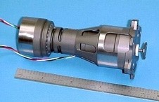
NASA had let three contracts for the development of nanometer-class structural actuators that had to operate over the temperature range of 30 K to 320 K with repeatability of less than 10 nanometers.  AEH won one of the contracts and produced the only working prototype, when tested in NASA labs.  And the Rubicon won AEH a position on one of the teams, George’s team as it turned out, vying for the James Webb Space Telescope.

George’s firm missed the contract, sadly, but he tells me the Rubicon actuators worked flawlessly and are alive and well in some warehouse in Huntsville.  (Or is it Area 51 in New Mexico?)

Its a Small, Small World indeed!  And what a mid-winter joy it was to meet some of you again.

Al H.
3-16-18

Optomechanics – Ivory > Nastran > Excel

Colleagues:

I have always found Excel to be one of the best optomechanical analysis tools. 

AEH has recently enhanced the Ivory3 Optomechanical Modeling Tools to make Nastran and Excel even more powerful for the optomechanical engineer.

It’s not that Nastran doesn’t do its job, but it’s only a finite element code.  For optical systems the engineer needs more methods and tools to interpret Nastran’s results opticallyIvory3 unleashes the power of Nastran into Excel to analyze optomechanical design issues:

Ivory3————————— into –>Nastran———- into —>Excel ——————-|

Optical prescription data    >   opto-structural model   >     LOS error contributors

In this example Ivory3 puts the image registration errors (ie. line-of-sight) into Nastran’s output file, both the net effect and the element-by-element effects, which may be cumulatively summed and plotted in Excel for the engineer’s assessment.  Obviously elements 1, 5 and 11 are the big drivers in this LOS error problem.

When you need to stabilize your image AEH has the tools! Al H.
3-8-18

Optomechanics – Secret Sauce

Colleagues:

Optomechanical engineers are a lot like professional chefs.  Each has a “secret sauce.”  Just like chefs we sample and adjust our sauces all the time to be sure they’ll come out consistently good.

AEH’s secret sauce is selections from W. J. Smith and R. J. Roark blended into K-J. Bathe.  Below I use the optical prescription to determine the optomechanical constraint equations (OCE) between each of its ten optical elements and the image on the detector (pink).  I then estimate the required stiffness properties of the structure between the elements, I define a lumped mass for each of the optical elements and connect them together with the nine beams (yellow) with the (estimated) proper stiffnesses.  I run it for the LOS error:

This initial run is usually off-target but it provides a starting point.  I replace the lumped masses with the actual lenses (from step files) and adjust the stiffness of the beams until I’m in the ballpark of the required LOS error.  Then I guide the design of the CAD structure to have the proper proportions to meet the required LOS error…

Voi-la!

1.3 ur rms . . . LOS . . .  1.4 ur rms
from Proposal    ——————————————————>    to Product.

AEH’s sauce provides the project a continuous and traceable record of the adequacy of the structural stiffness supporting the optical system from the earliest concepts to the final tested product.  AEH’s sauce is a little different every time, just like its culinary counterpart.

Bon appetite!

Al H.
2-7-18

Optomechanics – Zoom Lenses

Colleagues:

Zoom lenses are getting hot again.  They seem to come in cycles for AEH.

There was the 20:1 MWIR zoom with a 300 mm entrance pupil.  It was a lot of fun!  Good for a mechanical engineer to cut his teeth on too.  As tough as it was, it actually inspired much of AEH’s optomechanical engineering practice.

The 8:1 visible microscope zoom for medical diagnostics was an application that brought its own challenges.  Using commercial optical assemblies where only the focal lengths were known required some lab work to find their principal points.  Those of you who’ve taken my short course in optomechanical analysis or used my Ivory Optomechanical Modeling Tools will appreciate that need.

Then there was the 10:1 NIR zoom with 36 individual images, five moving lens groups and two working distances.  And it had to be packaged into a convenient instrument case.  AEH used a customized version of the Ivory Optomechanical Modeling Tools to make that one happen too.  One of the advantages of having the source code is that I can make it do whatever is needed at the time.  And the current version’s users receive the upgrades as I develop them.

It’s a New Year with new opportunities and new challenges.  As I said last time,

Here we go-o-o-o-o-o…….

Al H.
1-9-18

Optomechanics – So Many Tiger Teams

Colleagues:

Hold that Tiger…

I told you a while ago about attending a Massachusetts “TigerTeam” review of an external store for the F-16.  It took three days of talking about everything else to finally get to the crux:  High thermal gradients in the slab made the cavity unstable!  Surprise, surprise!  After the final session I got a tour of the brassboard’s laboratory.  The mechanical engineer confided to me that the brassboard would not work when it was up-side-down (talk about a tender cavity structure for a tactical aircraft application).

I’ve also told you about the two day “Tiger Team” in Texas for a laser, the brassboard of which worked just fine but the flight system lost power when a laboratory door was opened or closed.  In the final session the mechanical engineers described how the system’s flexure mounts for the cavity had been replaced (since they were not space-rated) with hex-head bolts!

Then there was the four-day “Tiger Team” in Illinois that reviewed the flight tests for a two-color recce system.  When I asked to see the imagery they declined and when I pressed for some quantitative data on the image quality they said they were unable to measure it.  And that was their “improved” design.

And the Culver City “Tiger Team” that couldn’t get their encrypted light back into their fibers.  The optical designer and I both stumbled onto the fix for that one at the same time.

Well, the Massachusetts folks managed to pull it out and Culver City folks went into production in Texas.  As “Tiger Teaming” goes two out of four ain’t bad.

…and, here comes 2018.  Hold onto your hats too!!!

Al H.
1-5-18