Optomechanics – Rubicon Actuator and NASA

Colleagues:

It’s a Small World!

A short time ago AEH was recruited, somewhat blindly I thought, to sit  on a “Red Team” to review a challenging zoom lens design.  I say “somewhat blindly” because I had never met nor corresponded with the client.  I had been referred to him by a third party.  Anyway, I accepted the assignment and went to a remote corner of Massachusetts in the dead of Winter to “throw darts” in a dark room.

Much to my surprise I knew the optical designer quite well.  We had worked together on a laser projection entertainment system some 25 years earlier and 2,500 miles West.  It was grand to see him again but the lights soon dimmed and I was invited to my chair to organize my darts for the day. 

But, the world got even smaller.  The “Red Team” was composed of individuals from at least a half-dozen different organizations, all with some interest in the project, and at lunch break I sat next to a man named George who seemed to know me, or know of me.  At one point he enquired about the Rubicon cryogenic actuator! I admitted to being its inventer/developer.

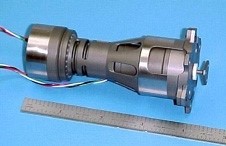
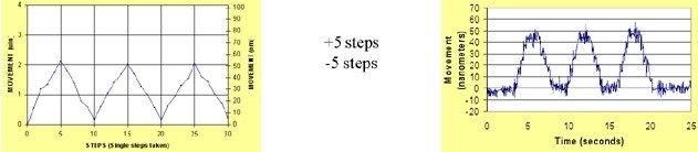
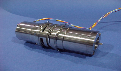
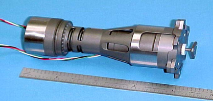
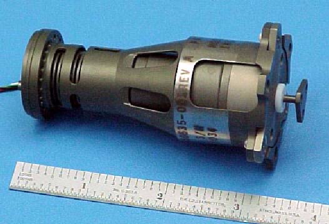
320 deg. K                              27 deg. K
NASA had let three contracts for the development of nanometer-class structural actuators that had to operate over the temperature range of 30 K to 320 K with repeatability of less than 10 nanometers.  AEH won one of the contracts and produced the only working prototype, when tested in NASA labs.  And the Rubicon won AEH a position on one of the teams, George’s team as it turned out, vying for the James Webb Space Telescope.

George’s firm missed the contract, sadly, but he tells me the Rubicon actuators worked flawlessly and are alive and well in some warehouse in Huntsville.  (Or is it Area 51 in New Mexico?)

Its a Small, Small World indeed!  And what a mid-winter joy it was to meet some of you again.

Al H.
3-16-18

Optomechanics – LCD Design Built Right from the Beginning

Colleagues:

Do you remember the Great LCD Projector Wars?  I certainly do! 

One of AEH’s jobs was to align three LCD images on the screen to 1/10th pixel accuracy and hold them there over long periods of time and over large swings of temperature.  The alignment was performed with adjustable fold mirrors to control the Tx, Ty and Rz degrees of freedom of each image.  A simple Ivory-in- Excel analysis told us it required a stroke of 17 mr. and a resolution of 0.00026 mr. on each of the fold mirrors.

AEH had some other resources to bring to the table as well.  We were able to adapt AEH’s patented set-n-forget actuator technology (Intended for JWST) to the design and manufacture of the mirror mounts.  There was a bit of a breathless interval, however, because AEH could not measure the sub-microradian resolution.  The test was to install the mounts and turn on the projector.  The system worked wonderfully, which verified the precision of the mirror mounts and the Ivory analysis.

Here’s to taking care of three images!

Well, that was then and now is NOW. 

The great September 1/4 off sale of AEH/Ivory 3.0 Optomechanical Modeling Tools has only a few more days to run!  Reserve your copy today.

Happy Autumn.

Al H.
9-23-15

Optomechanics – What do Optomechanics do all day?

Colleagues:

What does the optomechanical engineer bring to the table?  Hmmm…

A  few months ago a structural engineer friend asked me to analyze the strength of a lens assembly that he didn’t feel comfortable with.  It was injection-molded plastic, elastomeric rubber and glass.  OK…

Before that an optics friend challenged me to explain why it might be OK to mount glass lenses between threaded aluminum rings.  So, I did, but it took a while…

Another optics friend got me involved in resolving intellectual property disputes for mechanisms in cinematography lens assemblies…

Then a mechanical engineer friend needed a mass properties trade-off study between BK7 and sapphire for an airborne surveillance window…

Then another optics friend inquired about the possibility of nanometer-class structural actuators for 30 degrees K space optics.  So I designed, built and tested a successful set of them…

And before that I was asked to rationalize the structural damping coefficients to be used in an optical image jitter analysis.

The optomechanical engineer thinks outside the box.  He needs to work outside the box as well. 

Actually, I got that backwards:  He needs to work outside the box in order to be able to think outside the box.  It’s the peculiar demands, outside of his art, placed on the mechanical engineer by optics that inspire in him the intellectual curiosity to find workable engineering solutions.

Besides, he gets to enjoy your occasional company, too.  Thank you.

And, don’t forget to submit your abstract for “Optomechanical Engineering 2015.”
Assure your position in the program now:
         http://spie.org/OPO/conferencedetails/optomechanics
Hmmm… which one should I submit? 

Al H.
12-1-14

About the Rubicon Single and Dual Stage Actuators

About the Rubicon Single and Dual Stage Actuators

The Rubicon actuator resulted from a competition that was initiated by NASA.  In 1996 the Langley Research Center let four contracts for development of actuators suitable for deformable mirror applications.  The Rubicon actuator was the only one to complete its testing and deliver a prototype device along with the final report1.  Figure 1 shows the

Figure 1.  Initial Rubicon prototype actuator.

prototype device delivered on that contract.  This actuator was tested by NASA’s Jet Propulsion Laboratory (a task required by the Langley contract) at both room temperature (300 K) and cryogenic temperature (25 K) and found to satisfy the requirements for a space-quality structural actuator suitable for controlling the figure of primary mirrors.  It was a two-stage device with a stroke of 10 millimeters (coarse stage) and a repeatability of 3.8 nanometers (fine stage) with excellent stability, low power dissipation and complete set-and-forget capability.

The Rubicon actuator was subsequently adopted by Goodrich Corporation for their development effort on NASA Marshall’s Advanced Mirror System Demonstrator project.  Two new actuators were designed around Goodrich’s requirements:  A new two-stage actuator with 8 millimeters of stroke (coarse) and 9 nanometers repeatability (fine) and a new single-stage fine actuator with 90 micrometers of stroke and 9 nanometers repeatability.  A sectional view of the new two-stage Rubicon actuator is shown in Figure 2.

Figure 2.  Dual-stage Rubicon actuator cross-section.

It shows the coarse drive motor on the left that drives the output bracket (on the right) by a lead-nut driven pushrod.  The pushrod travels 9 millimeters along the axis of the actuator.  The fine stage controls the position of the coarse stage and the pushrod.  It is located between the coarse drive motor on the left and the mounting surface at the right.  The fine drive motor turns a harmonic drive unit (reduction of 100:1) that in turn drives a lead-screw.  The nut on the lead-screw compresses a coil spring that pushes against the housing of the coarse drive motor.  The compression in the spring creates a tensile load in the cylindrical housing of the actuator and by changing the spring loading the length of the cylindrical housing may be changed by small amounts.  The position of the output bracket (on the right) is therefore controlled by the sum of the displacements of the coarse (lead-nut driving the pushrod) and fine (extension and contraction of the cylindrical housing) stages of the actuator.  Large and small motions may be generated by driving either the coarse or fine drive motors (or both, as the operator desires). 

Since both motors are stepping-type motors they can be driven to a desired position by a controller that counts the steps.  When the current is removed the detent torque of the motors hold the actuator in position.  All materials of construction are aerospace-grade structural metals (stainless steel and titanium) and can be designed to support great loads with high reliability.

Photographs of both the single-stage and the dual-stage Rubicon actuators are shown in Figure 3.

a) Dual-stage Rubicon actuator

b) Single-stage Rubicon actuator

Figure 3.  a) Dual-stage and b) single-stage Rubicon actuators.