Optomechanics* – Jade Brittle Fracture Analysis Tool

*A note from Teale Hatheway: As I pored over Dad’s emails to organize and archive AEH’s Optomechanics Newsletter, I came across this gem which, dated 7-18-18, was never shared. I also discovered an abundance of conversations sparked by these communications. It’s no wonder Dad enjoyed his work well past “retirement age”: your camaraderie combined with his intellectual pursuits gave him great joy. He would’ve called it “sport.” With well over 100 Optomechanics Newsletters published since 2006, the experience of compiling these brought me renewed clarity on Al’s life work. From AEH product announcements, to carefully worded client stories, to occasionally revealing his trade secrets, I hope you will continue to enjoy his wit and his wisdom here… So here we go! The last Optomechanics. I sure hope he finished editing it. Enjoy!

———–

Colleagues:

Put fracture mechanics to work for you!

Fracture mechanics says that glass is sensitive to static stress corrosion fatigue effects.  Glass parts have finite fatigue lives when operated in a normal moist environment.  If the fatigue life, T, is defined as the time to fracture under the conditions of service, that life may be calculated from

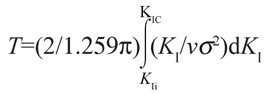
noting that KIi is the initial stress intensity, KI is the instantaneous stress intensity, KIc is the fracture toughness, v is the instantaneous crack growth rate and the local stress, s, is time-variable and it is inside the integral.

AEH recruits our Jade Brittle Fracture Analysis Tool, to perform the numerical integration and determine T, the fatigue life.  For Jade it’s a piece of cake!

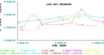
For instance, take this thermal-structural stress transient for an aircraft’s window requiring 10,000 flight hours of service life:

 FULL STRESS CYCLES AT FRACTURE= 3563
TIME TO FRACTURE= 44896587.75 
SECONDS= 12471.274375 HOURS
CRITICAL INITIAL TENSILE STRESS= 55002270.5466022
INITIAL CRACK DEPTH= .000149 

If the engineer applies a reasonable factor of safety, say 1.5, to the critical initial tensile stress (the ultimate load) it will provide a proof test load (82.5 MPa in this case) that will assure the safety of the window throughout its service life.

There’s no way to get there with closed-form solutions and it’s way too big for an Excel spreadsheet.  Jade goes through the complete calculation in just seconds, allowing the engineer to try various combinations of design variables to optimize a safe concept.

Jade Brittle Fracture Analysis Tool
Now available from AEH.

Al H.
7-18-18

Optomechanics – Secret Sauce

Colleagues:

Optomechanical engineers are a lot like professional chefs.  Each has a “secret sauce.”  Just like chefs we sample and adjust our sauces all the time to be sure they’ll come out consistently good.

AEH’s secret sauce is selections from W. J. Smith and R. J. Roark blended into K-J. Bathe.  Below I use the optical prescription to determine the optomechanical constraint equations (OCE) between each of its ten optical elements and the image on the detector (pink).  I then estimate the required stiffness properties of the structure between the elements, I define a lumped mass for each of the optical elements and connect them together with the nine beams (yellow) with the (estimated) proper stiffnesses.  I run it for the LOS error:

This initial run is usually off-target but it provides a starting point.  I replace the lumped masses with the actual lenses (from step files) and adjust the stiffness of the beams until I’m in the ballpark of the required LOS error.  Then I guide the design of the CAD structure to have the proper proportions to meet the required LOS error…

Voi-la!

1.3 ur rms . . . LOS . . .  1.4 ur rms
from Proposal    ——————————————————>    to Product.

AEH’s sauce provides the project a continuous and traceable record of the adequacy of the structural stiffness supporting the optical system from the earliest concepts to the final tested product.  AEH’s sauce is a little different every time, just like its culinary counterpart.

Bon appetite!

Al H.
2-7-18

Optomechanics – Unified Approach to Thermal Structural Optical Analysis

Colleagues:

Optics is a crazy industry.  We’re so dedicated to the digital computer that we often overlook underlying realities.  That’s especially true in the mechanical engineering art of heat transfer.  Management structures have insisted on each discipline using its own software which has Balkanized the disciplines of structures and heat transfer: i.e., the temperatures must be analyzed in a finite difference (FD) code and the results imported to a finite element (FE) code.  The importation involves extensive extrapolation and interpolation of the FD data to the much larger (often by two or three orders of magnitude) of the FE data-set and it can lead to some peculiar results.

AEH has long preferred a more Unified approach:  Select a code that can do them both, usually an FE code, and use engineering judgement to adapt the other discipline (usually a few boundary temperatures).  It usually requires several runs of the problem to assure that the underlying assumptions of the adaptation were appropriate but they go much faster than the Balkanized approach (and, often, more accurately for the optics behavior).

It’s the thermal-structural-optical method I used on the LACE Ultra-Violet Plume Instrument, which made Aviation Week’s75th Anniversary Issue.  Check out the UV plume image from AW’s cover, above!

More recently, a colleague was directed to thermally analyze an optical system in CFD and I was to apply his temperatures and gradients to calculate the boresight errors among the optical instruments.  Well, what he was handing me made no sense at all.  So, I added heat transfer terms to my opto-structural FE model and ran the operational transient of concern to the project.  The thermo-structural-optical results were spot-on.

There are a lot of ways that an engineer needs to keep his tools sharp.  And they require maintaining confidence in the analytical methods as well.

More later.  Happy Holloween!!!!!

Al H.
10-23-17

Optomechanics – MatLab Models and Ivory

Colleagues:

Hey, Control Systems Engineers, this one’s for you!  I’m sure you remember my dear friend who likes to declare, “You have to know the answer before you do the analysis!”  And his wicked “eye-twinkle” was part of that message too.  I used him then as a vehicle to highlight the importance of engineers making estimates and developing a “sense of smell” about the quality of their decisions.

So, my question for you is:  How do you incorporate the line-of-sight into the MatLab model of your “stabilized” optical system?

Well, AEH knows of three ways:  1) You can calculate it yourself, from the optical prescription, and insert it in your MatLab file, with some luck, or 2) you can copy the Optomechanical Constraint Equations (OCE) from Ivory and patch them into your Matlab file, with a little better luck, or 3) you can speak nicely enough to the structural engineer for him or her to import the OCE (from Ivory) into his FE model and the resulting eigenvectors, BINGO and…

If you want to learn more here’s an opportunity:  On August 7th, all day, I’ll be teaching my course, Optomechanical Analysis, for SPIE’s Symposium Optics+Photonics 2017 at San Diego’s Convention Center and Marriott Marina Hotel.  The first half of the course is all about the OCE, how you generate them and how they’re used.  Then you might stick around for our Conference, Optomechanics 2017, on the 8th and 9th to find out what everyone else is doing.  On Tuesday evening, the 8th, I’ll be hosting a meeting of the Optomechanical Technical Group between 8 and 10.  Dan Vukobratovich will be our principal speaker followed by an open discussion.

Yeah, you guessed it.  My dear friend is a control systems engineer.  One of the things I did for him was to assure that the structural engineer incorporated Ivory’s OCE into the FE model that produced the eigenvectors he used in MatLab to design the control system.  Later system tests on the shaker-table confirmed the quality “smell” of this decision.  Ivory nailed it, dead-on!

I’ll see all of you in San Diego!

Al H.
7-10-17

Optomechanics – SOLVED: Differential equations of elasticity for the maximum tensile stress in glass…

Colleagues:

Those of you who are familiar with my expression,

s(x)=-s(y)=pb(1-2v)/(a+b)^2,

for tensile stresses in a ring-mounted glass lens (SPIE, 7424-14, 2009) should be delighted to know I didn’t give up there.  I recently solved the differential equations of elasticity for the maximum tensile stress in the glass for a short line-contact load,

s(x)=-s(y)<P(1-2v)/(2pL^2).

In this expression s(x) is the tensile stress, s(y) is the compressive stress, P is the total load, v is Poisson’s ratio for the glass and L is the length of the line contact. 

As in the prior case these stresses are much lower (by factors of perhaps 1/1,000 to 1/1,000,000 depending on the length L) than those predicted by the erroneous Delgado and Hallinan method used by optical engineers since the 1970s.  In the limits, where L approaches either 0.0 or infinity, my expression approaches those in the classic literature (ie., Timoshenko and Goodier), just as it should. 

And it worked!  The low stress level opens up a whole new family of design options.  Just another one of those “small things” that brings joy to an optomechanical engineer’s heart. 

Oh, in my new expression “<” means “less than” because I integrated only over the length, L, assuming the contact width was infinitesimal.  That suited my engineering (worst case) purpose.  There’s still time for some grad student to integrate over the finite width for the full solution.

We’re just keeping AEH’s tools sharp, too.

Oh, October… the Great Goblin was enchanting but the little kids were TRULY GREAT!!!

Al H.
11-2-15

Optomechanics – Prepare for Success Early

Colleagues:

Optics is an art that’s just meant to work… until it doesn’t. 

The optomechanical engineer’s job is to survey the available mechanical design spaces looking for optical problems.  The engineer identifies the problems early, gets on top of them and stays on top all the way through.  MSC Software Corporation recently published a Case Study on this subject.  Here’s the link—

Optomechanics at MSC

Many problems can be anticipated and avoided by using relatively simple, lumped-parameter models in the beginning of a project.  If the project waits until the distributed properties are well defined it may be too late and the budget and schedule considerations may even shut the project down.  Optomechanical analysis is at least an order of magnitude trickier than the individual disciplines alone.  So the engineer has to have tools, and that means being able to couple the structure to the optical behavior in a single code.  AEH uses MSC/Nastran and AEH/Ivory.

Here are two examples, one a success the other a failure.  Both were gimbal-stabilized telescopes of roughly the same size:

The failure was a project that would not let the lumped parameter LOS model be run in the beginning but insisted that the analysis model be prepared from the finished engineering drawings.  The full-up analysis showed an unstable LOS.  Redesigned solutions were possible but costly. This project was cancelled. 

The successful project was able to demonstrate sufficient margin of safety with the lumped parameter LOS model that a full-up optomechanical model wasn’t needed.  The structural engineers could concentrate on strength and safety.  This project was fielded. 

Neither outcome was intuitive or obvious at the projects’ beginnings but their results couldn’t have been more stark.

Powerful tools, simple models, early in the project:  The eye-candy may be poor but the numbers can save the engineer’s buttons.

Spring is lovely in Pasadena.  I hope you’re enjoying it as much as I am.

Al H.
5-14-15

Optomechanics – Bad Behavior in Complex Systems

Colleagues:

One of the challenges for a mechanical engineer is to determine the dominant drivers of bad behavior in complex systems.  The behavior may be observed during service, in environmental tests or system analyses.

In optical systems AEH segregates the effects of each degree of freedom (Tx, Ty, Tz, Rx, Ry, Rz) of each optical element (1, 2, 3, …, detector) and plots the cumulative sum which, in the case below, exposes the major offending elements to be 1 and 5 (see chart).  The engineer may then objectively recommend structural design changes that will stabilize the offending optical elements and improve the optical performance of the structure.

I’ll be presenting the details of this approach in a paper during SPIE’s Optics+Photonics Symposium in San Diego this August.  I hope to see you all there.

In the meantime, if you have questions just give me a call.  I’ll be here.

Happy St. Patty’s Day.

N’Blarney ‘ere, b’Gorah!

Al H.
3-9-15

Optomechanics – The Calibrated Thumb Technique

Colleagues:

One of my early bosses, Wilford, introduced me to the “calibrated thumb” technique.  The immediate challenge was to anticipate static deflections and resonant frequencies in new design work.  His broader purpose was (I have since come to think) to open my mind about ways to develop my estimating skills.  I was working in airborne IR countermeasures at the time. 

I’ll introduce the technique to you with a much more recent example. 

I had been called in to make dynamic boresight stability analyses for a multi-sensor suite.  It was presented to me as an all-up finite element solid model of the system with three million-plus degrees of freedom.  I incorporated Ivory’s optomechanical constraint equations to calculate the line-of-sight errors for each sensor and the boresight errors between them.  This unified optomechanical model passed the rigid-body checks and static gravity checks just fine.  The calculated boresight errors were small compared to the specification. 

But I had an uneasiness.  There are lots of places in complex models to enter typos, select the wrong property from a long list or drop some decimal places.  How can I settle my uneasiness about someone else’s model?  My client had been around a while and done a lot of good stuff in the past, so I got an idea.

I went out to their shop where a variety of similar sensor systems were sitting on granite surface plates.  I got a height gage with a digital indicator and set it next to one of the systems.  Then I pushed on the system with my thumb applying what I thought to be about 1.0 pound and observed the deflection under the digital indicator’s tip.  I repeated it with two other sets of hardware in the shop.  The deflections were all somewhat different.  That was expected since the systems were of substantially different sizes.  But they’d all been designed and built by this organization.

Then I did a thought experiment, “If I push on the unified model with my thumb how much deflection should I expect?”

I went back to my computer and applied a similar load to the model.  The computed response compared well to my thought experiment.  My anxiety eased and the model proved, in test, to be reasonably accurate.  Whew!

A calibrated thumb is a good thing to have.  Thanks, Wilford.

Of course, my calibrated thumb is one of the tools I try to keep sharp.  When I got back to my home office I checked my thumb with a postal package scale.

Use it or loose it!

Al H.
1-29-15

Optomechanics – Overcoming the Optical Lexicon for Mechanical Engineers

Colleagues:

Reflecting on the year just (barely) passed a couple of older stories keep coming to mind. 

Early-on, a lens designer friend, Tom, asked me to mount an afocal triplet in a weapon sight.  He said he wanted it to be on a kinematic mount.  I hadn’t heard the term “kinematic mount” before so I did a little research.  Mark’s Handbook had no entry.  Maleev and Hartman’s Machine Design had no entry.  Ham and Crane’s Mechanics of Machinery had no entry.  Sears and Zemansky’s University Physics was not helpful.  Finally, in J. L. Meriam’s Mechanics, Part 2, I found a partial definition, “kinematics … the study of the motions of bodies without reference to the forces which cause the motions….”  I went back to Tom and asked him,  “What kind of mount for optics in a weapon sight doesn’t consider the forces involved?”  Well, he was patient in explaining his higher level of abstract reasoning and suggested that I expand my library. 

Some time later I was sent by the Air Force to a design review in Texas and to report what I found.  I wrote you about this a year or so ago.  The physicists had designed one of the hottest doubled-YAG lasers I’d ever seen and they requested that the cavity be installed on a kinematic mount.  The engineers complied with a classic three-ball mount.  It worked like a champ in the brassboard but the flight unit was unstable.  Everyone was perplexed.  Well, it turned out that the kinematic mount wouldn’t survive the service vibration so the mechanical engineers had conveniently provided screws at each of the balls to lock them out for flight.

In the first case Tom and I worked it out, I ate my humble pie and Tom put me on his patent as a co-inventor.  In the second case the Air Force lost faith in the contractor and cancelled the entire project.

One of the challenges faced by mechanical engineers in the optics industry is lexical:  The engineer may hear what is said but not clearly understand what is meant.

To address this challenge the engineer must ferret-out the acceptable mechanical behavior, regardless of how it was originally expressed, and design it into the required structures and mechanisms.  It takes a little extra digging but has proved to be a winning strategy.

And with that. . . A Happy New Year to you all!

Al H.
1-5-15

Optomechanics – Early Adoption Matters

Colleagues:

At AEH we study closely the ways things fail.

It is often said that an engineer’s job is to make things work.  Well, that’s nice.  Tinkerers can do that too.  What’s really required from engineers is to make things work every time.  That’s a little different discipline. 

So, as engineers AEH studies how things fail in order to better know how to prevent bad things from happening:

In optical systems, virtually all “optical” failures result from some defect in the mechanical implementation.  These failures are never corrected by changing the optical prescription.  Well, almost never:  There was the Hubbell primary mirror fix.

Optomechanical problems are best spotted early, while the design resources (size, shape, mass, arrangement, interfaces, etc.) are malleable.  Those resources can quickly become depleted, even unavailable, as they are claimed by other interests:  bearings, servos, electronics, cryogenics, subcontractors, etc.

Early detection requires special tools for the optomechanical engineer.  To assess optomechanical problems the optics and mechanics must be coupled by the engineer, hopefully from the first publication of the prescription, perhaps during the proposal effort even. 

The results of this early optomechanical coupling may only be estimates, but they’re essential.  They give the engineer who uses them a sense of how to guide the design to his desired…, no, to his required destination: 

Spot-on performance with a trouble-free service life.

Early assessment of optomechanical problems is one way we help our clients.  AEH has the tools:  longhand, ten-key, spreadsheet and Nastran. We’ve got all that plus Ivory, Ebony and Jade to interpret the optomechanics for you.

Of course, we can often help after problems materialize and the corrective options have become more restricted.

Joy to all for the Autumn season.  It has arrived!

Al H.
10-6-14