Optomechanics – Adhesive Mounting of Mirrors

Colleagues:

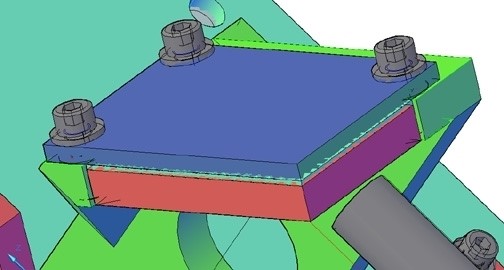
Let me revisit my engineering tool for adhesive mounting of mirrors:

Those of you who have studied the source reference (SPIE: 6665-03, 2007) know now that it guides the engineer to elastomeric adhesives for the mounting.  The reason for this is that hard adhesives have a high modulus of rigildity, G. This fact leads to large optical distortions of the mirror surface due to differential thermal expansion and contraction between the mirror and the mount.  But, for elastomers their low modulus of rigidity tends to isolate the mirror from the differential expansion and contraction of the mount.  The reduction in surface distortion may be a factor of between two to three orders of magnitude using an elastomer compared to a hard adhesive.
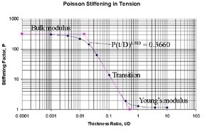
Simultaneously, Poisson stiffening tends to stabilize the position of the mirror’s surface.  It increases, by a similar factor of 100 to 1,000, the apparent tension/compression modulus, K‘, of the elastomer between the mirror and the mount (comparing K’ to the Young’s modulus, E).  The bulk modulus, K, for a silicone elastomer is typically in the range of 150,000 psi to 200,000 psi whereas its modulus of rigidity may be as low as 180 psi to 200 psi.  In thin adhesive layers the apparent tension/compression modulus, K’, approaches the bulk modulus, K.  Since the Young’s modulus would be about 570 psi, which becomes a Stiffening Factor of about 300 (see above).  The low modulus of rigidity assures small shear stresses in the bondline due to thermal expansion and contraction while the high bulk modulus stabilizes the mirror’s surface in the optical path.

Perhaps you begin to see why this tool is really not a rule-of-thumb.  It is an engineering technique for tailoring the thickness, t, of a specific elastomeric adhesive, G, to the properties of the mirror, the properties of the mount and the thermal environment the assembly will see in service.  It also requires the engineer have some understanding of the Poisson stiffening effect in thin bondlines.

I hope the Holidays left you all refreshed and eager for the New Year.  Here we go again!

Al H.
1-10-12

Optomechanics – Minimum Adhesive Thickness

Colleagues:

Wherever I visit, rules-of-thumb are a hot button topic these days.  My normal response has been that engineers are expected to do better than use rules-of-thumb.  But Fall is here and the Holidays are close-at-hand, so allow me to be a little more responsive this time. 

I develop engineering tools and skills to support and guide my engineering interests.  For instance, I have developed techniques to analyze the surface figure errors introduced by element mounting techniques.  In the spirit of the coming Season, I will give to one and all (yes, even to Tiny Tim) one of my engineering tools:

It tells the engineer the minimum adhesive thickness necessary to limit the thermal distortion of a mounted mirror.  It is easier to use than a finite element code and probably more accurate.

I do not, myself, consider the above expression a rule-of-thumb but rather one of several engineering tools for use in these kinds of problems.  The curious may read my original paper, SPIE: 6665-03, 2007.  The expression is formed by substituting equation (6) into equation (10), both from the subject paper.  I hope you find it as useful as I have.  It’s about as close as I get to a rule-of-thumb in my practice.

Now, let us turn to the approaching Season:  The Joyous, Tumultuous, Boisterous, Extravagant Holiday Season from All-Hallows Eve to Twelfth-Night.

We can talk about engineering tools, and rules-of-thumb, any old time.

We should Enjoy and take Cheer Now!

Al H.
10-24-11

Optomechanics – Engineered Design

Colleagues:

“To design or to analyze?  Aye, that is the question.”  My apologies to the Bard.

I spent the first half of my career in design.  But even as a designer I was always a numbers guy.  I wanted to know why some things worked and others did not.  And I found that the numbers could actually help explain the workings of things.  An example:

I designed the first IR missile active jammer to go into the Navy’s service (AN-ALQ-123).  The IR source was fragile and had never been qualified for military use.  I was frustrated by the reluctance of the structural engineering department to support me.  They wouldn’t touch the quartz, Lucalox and niobium that the source was made from.  Nor would they let me anywhere near their finite element code.  So, I had to run the tests to determine its fragility and then analyze my mounting design to assure that the IR source could survive the “cats-n-traps” of carrier take-offs and landings. I even had to write my own source code for the analysis.  It worked!  The design was a grand success and hundreds of -123s entered the Navy’s inventory.  It even made the cover of the Old Crows monthly magazine.  I was a proud papa.

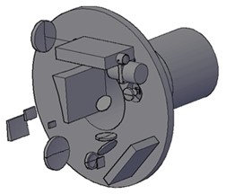
I still design.  Here’s a view of a newer design job.  It’s an active stand-off sensor

consisting of a zoom lens with five moving lens groups, all servo controlled, plus a sixth movable lens group to control the focus at a distant target.  I gave my client all of my design files and they took it from there.  The last I heard, the prototype was working just fine.  There’s a really hard part to design consulting though: Letting someone else adopt the offspring.

Numbers are a lot less sentimental.  I do a lot of analysis these days but I still think as a designer.  Luckily, as an engineer I can work both sides of that street. 

I’ll be talking-up my design tools to the analysis folks at the MSC Software Users’ Conference in Santa Ana on October 5th.  (Just as I talked-up my analysis tools to the design folks at the SPIE Symposium in August.) 

Will I see a few of your cheerful faces there on the 5th?

Al H.
9-26-11

Optomechanics – SPIE

Colleagues:

There’s a great opportunity for optomechanical engineers coming up next month in San Diego:

SPIE’s International Symposium on Optics and Photonics
August 22-25, 2011
San Diego Convention Center and Marriott Marina Hotel

We (The International Technical Group on Optomechanical Engineering) have a two-day conference
on the 24th and 25th with 31 oral presentations and 6 poster presentations.  The topics cover the whole spectrum of optomechanics from materials through components and mounting to systems performance and applications.  Hot stuff.

We’ll have an evening meeting as well:  Tuesday, 800 to 1000 PM (check the conference program for the hotel room).  Our feature speaker will be Kent Weed of Lightworks Optics in Irvine, California.  He’ll discuss, among other things, LIghtwork’s challenges in a recent project to map the surface of the moon.  They’ve had some really interesting projects and this should be a fascinating gathering.  The meeting is free and open to the public.

If any of you have items you’d like to put before the Technical Group let me know and I’ll make sure you have a spot on the agenda.  Following the agenda items we’ll have our usual “Problems and Solutions Workshop,” which will last as long as your energy and the Hotel management allow.

Oh, I almost forgot, I’ll be giving my tutorial on the Optomechanical Constraint Equations,

Optomechanics and the Tolerancing of Instruments (or The Mechanics of Image Motion).
Tuesday, August 23, 2011, 830 AM to 500 PM
San Diego Convention Center

This is the in-depth explication of the theory and application of optomechanical influence coefficients in the mechanical design and analysis of optical instruments.  You may  register for the class through the SPIE web site:  http://spie.org.

There’ll be a massive three-day exhibit with all of our suppliers represented and Wednesday evening is the grand awards banquet… seemingly endless opportunities for socializing and networking with all the movers and shakers of the industry.

It’s going to be a great week and I hope to see you all there.

Al H.
7-20-11

Optomechanics – Who owns the error budget between the gyro and the imager?

Colleagues:

The optikers own it.  That turns out to be the answer, largely by default.

Well, servo engineering didn’t step forward.  Neither did structural engineering.  Mechanical engineering and mechanical design said, “That’s systems engineering.”  The systems engineer said, “It’s not in the requirements flow-down tree.”  Program management said, “Get me an answer!”  Project engineering responded that optical design has rules of thumb for everything, let them deal with it.  And that’s the last word I’ve heard, so far at least.  So guess who’s winning… the otpikers!  It’s their industry so they take the lead, I guess.

Now, do you remember the question?  It was, “Who owns the error budget between the gyro and the imager?”  (I know, it’s been two whole months but this is important.)

It just happens that I have what may be a helpful (if somewhat awkward) rule of thumb for the optikers:  The error between the imager’s LOS and the gyro will be at least two or three times as big as the error between the gyro and the resolver/encoder.  This rule has two addenda:  First, improving the gyro error will not improve the LOS error;  Second, the longer you wait the harder it gets.

The AEH rule has important implications for stabilized optical instruments (imagers, lasers, spectrometers, diffractometers, etc.):  In the margin it may be more cost effective to work to stabilize the LOS to the gyro than to stabilize the gyro to the base (or other reference).  Gasp!  Take a deep breath.  You’ll be OK. 

Another is that if you don’t do it early you won’t get to do it at all. Aarrrgh!  (Followed by silence.)

Just passing possibly useful insights on to my friends.  AEH and AEH Ivory are here to help.

The sunburn I picked up on Sunday was glorious (forgot my sunblock!).

Happy Summertime.

Al H.
7/12/11


Optomechanics – Ivory, MSC Patran/Nastran and MS Excel

Colleagues:

I wish to correct a misimpression.

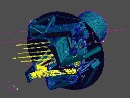
I illustrated my last note to you with a graphic of a stabilized inner (elevation) gimbal, with a laser transmitter, laser receiver, IR imager and a gyroscope.  Many of you assumed that was a CAD rendering or a meshed CAD model.  It was neither.  At the time that the FE model was prepared the CAD model could not support that level of detail.  All of that initial structural design on the inner gimbal was done with AEH Ivory in MSC Patran/Nastran supplemented with MS Excel.

Here’s a CAD graphic at the start the structural design on the elevation axis…

…and here’s that Patran graphic of the structural design concept developed from it. This was a design engineering task undertaken at the very start of the project, a trade-off study between pointing stability and on-gimbal mass.  I reduced the pointing error of the imager by 73% (39.6 mr to 10.6 mr) for a weight increase of just 18% (0.96 pounds).  Not a bad day’s work.  And I was able to give the CAD designer a reasonably stable design concept for mounting the imager.  That’s engineering.  The design trade-off study was made possible by the concurrent useof AEH Ivory, MSC Patran/Nastran and MS Excel during the formative early stage. 

Now for the important stuff.  Have you gotten your sun-block and water skis ready yet?

Al H.
6-14-11

Optomechanics – The Journal of Applied Remote Sensing

Colleagues:

It was a great gathering in Orlando last month: conferences, classes, banquets and above all friends.

I was invited to address a meeting of engineers whose topic was “Acquisition, Tracking, Pointing, and Laser Systems.”  I sat in a dark room staring at a bright screen and listened for two hours to electrical engineers talk about stabilizing lines-of-sight.  They all showed amazing slides of flow diagrams and control systems:  resolvers, torquers, Bode plots, gyros, transfer functions, encoders, phase margins, accelerometers, amplifiers, feedback loops, etc.  Not one single slide showed a line-of-sight, an optic, a laser beam or a target

I was last on the agenda.  I opened by pointing out that lines-of-sight and laser beams were real physical features, just as real as the axis of rotation of a gyro.  Then I demonstrated a way to link the lines-of-sight of imagers and lines-of-propagation of lasers to inertial sensors through elastic behavior of finite element models.  Then I showed an analysis in which the rms error between the gyro and the laser was about twice as big as the gyro’s rms error itself.  “Was the laser-to-gyro error in their budget,” I asked, “or in the optical designer’s?”  “What about the imager-to-gyro error?”  The audience seemed to have some difficulty answering my queries and also some framing their own, but they were very gracious.  We shook hands and then, suddenly it seemed, I was outside standing in the warm Spring afternoon sunlight.  Perhaps I’d been impertinent. 

A week or so later, back in the office, I received an invitation from the engineers to publish my remarks in their prestigious journal, The Journal of Applied Remote Sensing.  I guess I was not too impertinent.  It’s a fine balance;  someone has to identify the possibility, tickle the imagination, “stir the pot” and, sometimes, “serve the first dish”.  I’ve accepted this invitation too.

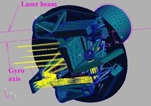
I have one relic from the event to commemorate it.  That’s the slide of mine showing a laser beam and an IR imager coupled to a gyro’s axis of rotation through a finite element structural model of a sensor suite.

It was in deed a great gathering in Orlando last month.  And, ahh… the friends!  Thank you all.

Now…  Summer is nigh.  Get out the sun-block and water skis.

Enjoy!

Al H.
5-31-11

Optomechanics – Training and a Party

Colleagues:

Well, Spring finally decided to arrive.  It was almost 60 degrees in Pasadena yesterday!

 And I’ll be going to Orlando shortly, on the 25th, to celebrate the season.  That’s not exactly true:  I’ll also be presenting a paper on how the mechanical engineer assures that the laser system and the imaging system stay aligned with the gyro (or other inertial sensors) in a stabilized sensor suite.  That’ll be on Tuesday morning, the 26th, about 11:40.

Then I’ll celebrate.  Oh, but only a little, because on Wednesday, the 27th, I teach class all day (Optomechanical Analysis).  Then I’ll really celebrate, at the banquet that night.
SPIE’s Symposium on Defense and Security is a great gathering!  I’ll be there most of the week and I hope I’ll see many of you there.
Come and celebrate too!

Al H.
4-12-11

Optomechanics – Training

Colleagues:

This is just a reminder that I’ll be presenting my full-day tutorial “Optomechanical Analysis” in Orlando on April 27th during SPIE’s Defense and Security Symposium.

The class is primarily for mechanical engineers who work in the design and analysis of optical instruments and systems.  But it may also be of interest to other professionals in the optics industry.  Review the course description and reserve a seat in the classroom.

I hope to see a great number of you in Orlando next month.

Al Hatheway
3-22-11


Optomechanics – Flat Surfaces

Colleagues:

This is a tale about the power of flats.

The IR sensor was out of focus and I drew the straw that said, “Measure the contraction in the focal plane support structure between room temperature and 80 K.”  Others drew different straws and the project turned itself inside-out to discover the root cause of the focus problem.  This system did not have an on-orbit focus control mechanism.  (Now, now!  I hear you clucking your tongues.  But, do you know how many successful systems do not have focus controls?  Enough!  It’s my story!)

Finally, the various straw-drawers were convened and none could find a millimeter of focus error, anywhere, adding up all our contributions.  After the meeting I was assigned to another project, as happens in large firms.  I eventually left the firm not knowing how the problem was resolved.

Some time later, at an Optical Society meeting, I was sitting with one of my erstwhile compatriots reminiscing.  He declared that the problem had been resolved and was not a design problem at all, just an unfortunate artifact of the test setup. 

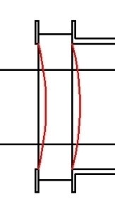
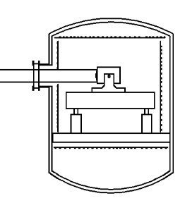
The germanium window in the vacuum tank sagged under the influence of the outside pressure (see the figure).  The resulting curvature of the surfaces created a meniscus lens with a small optical power ( about -5.E-08 diopters) but enough to cause the image to fall behind the focal plane by over a millimeter and send the project team into its flurry.

It’s a simple thing to check:  One equation from Roark for the deflection; a little geometry for the radius of curvature; the basic lens equation for the focal length and Ivory (or Zemax or CodeV or Oslo if you insist) for the focus error.  This firm was one of the old-line firms of Southern California aerospace and they were in space before I was out of college.  This was not their maiden voyage to low earth orbit. 

My compatriot’s uncritical views were colored (in my judgement) by his philosophical training as an optical designer.  As an engineer I was more jaundiced:  The engineer who designed the test should have seen this one coming and accommodated it (defocus the collimator, introduce a corrector lens, something).  But, it just got lost among the various groups who participated in the project.

My advice to optomechanical engineers:  Beware of flat optical elements; windows, wave plates, fold mirrors, etc.  Everyone, I mean everyone, is checking the components with any optical power.  The un-powered flat components get short shrift.  The results are often not seen until very late in the program and then they raise Holy Havoc with the engineer’s evenings and weekends.

I pass this anecdote along to you partly as a cautionary tale and partly as a celebration of the insight I gained from that compatriot one evening over a pleasant dinner at an Optical Society meeting.  That insight, pay extra attention to all the “flat” elements, has saved my buttons many times over the years since I left my former firm, uncertain about the sensor that didn’t focus.  Thanks, Bob.

The Holidays are coming and I hope you all enjoy a festive Season filled with friends, family and warm camaraderie.

Al Hatheway
11-16-10