Optomechanics – Who owns the error budget between the gyro and the imager?

Colleagues:

The optikers own it.  That turns out to be the answer, largely by default.

Well, servo engineering didn’t step forward.  Neither did structural engineering.  Mechanical engineering and mechanical design said, “That’s systems engineering.”  The systems engineer said, “It’s not in the requirements flow-down tree.”  Program management said, “Get me an answer!”  Project engineering responded that optical design has rules of thumb for everything, let them deal with it.  And that’s the last word I’ve heard, so far at least.  So guess who’s winning… the otpikers!  It’s their industry so they take the lead, I guess.

Now, do you remember the question?  It was, “Who owns the error budget between the gyro and the imager?”  (I know, it’s been two whole months but this is important.)

It just happens that I have what may be a helpful (if somewhat awkward) rule of thumb for the optikers:  The error between the imager’s LOS and the gyro will be at least two or three times as big as the error between the gyro and the resolver/encoder.  This rule has two addenda:  First, improving the gyro error will not improve the LOS error;  Second, the longer you wait the harder it gets.

The AEH rule has important implications for stabilized optical instruments (imagers, lasers, spectrometers, diffractometers, etc.):  In the margin it may be more cost effective to work to stabilize the LOS to the gyro than to stabilize the gyro to the base (or other reference).  Gasp!  Take a deep breath.  You’ll be OK. 

Another is that if you don’t do it early you won’t get to do it at all. Aarrrgh!  (Followed by silence.)

Just passing possibly useful insights on to my friends.  AEH and AEH Ivory are here to help.

The sunburn I picked up on Sunday was glorious (forgot my sunblock!).

Happy Summertime.

Al H.
7/12/11


Optomechanics – Ivory, MSC Patran/Nastran and MS Excel

Colleagues:

I wish to correct a misimpression.

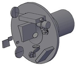
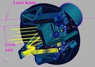
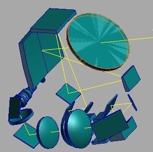
I illustrated my last note to you with a graphic of a stabilized inner (elevation) gimbal, with a laser transmitter, laser receiver, IR imager and a gyroscope.  Many of you assumed that was a CAD rendering or a meshed CAD model.  It was neither.  At the time that the FE model was prepared the CAD model could not support that level of detail.  All of that initial structural design on the inner gimbal was done with AEH Ivory in MSC Patran/Nastran supplemented with MS Excel.

Here’s a CAD graphic at the start the structural design on the elevation axis…

…and here’s that Patran graphic of the structural design concept developed from it. This was a design engineering task undertaken at the very start of the project, a trade-off study between pointing stability and on-gimbal mass.  I reduced the pointing error of the imager by 73% (39.6 mr to 10.6 mr) for a weight increase of just 18% (0.96 pounds).  Not a bad day’s work.  And I was able to give the CAD designer a reasonably stable design concept for mounting the imager.  That’s engineering.  The design trade-off study was made possible by the concurrent useof AEH Ivory, MSC Patran/Nastran and MS Excel during the formative early stage. 

Now for the important stuff.  Have you gotten your sun-block and water skis ready yet?

Al H.
6-14-11

Optomechanics – Flat Surfaces

Colleagues:

This is a tale about the power of flats.

The IR sensor was out of focus and I drew the straw that said, “Measure the contraction in the focal plane support structure between room temperature and 80 K.”  Others drew different straws and the project turned itself inside-out to discover the root cause of the focus problem.  This system did not have an on-orbit focus control mechanism.  (Now, now!  I hear you clucking your tongues.  But, do you know how many successful systems do not have focus controls?  Enough!  It’s my story!)

Finally, the various straw-drawers were convened and none could find a millimeter of focus error, anywhere, adding up all our contributions.  After the meeting I was assigned to another project, as happens in large firms.  I eventually left the firm not knowing how the problem was resolved.

Some time later, at an Optical Society meeting, I was sitting with one of my erstwhile compatriots reminiscing.  He declared that the problem had been resolved and was not a design problem at all, just an unfortunate artifact of the test setup. 

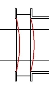
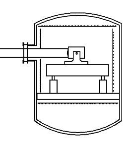
The germanium window in the vacuum tank sagged under the influence of the outside pressure (see the figure).  The resulting curvature of the surfaces created a meniscus lens with a small optical power ( about -5.E-08 diopters) but enough to cause the image to fall behind the focal plane by over a millimeter and send the project team into its flurry.

It’s a simple thing to check:  One equation from Roark for the deflection; a little geometry for the radius of curvature; the basic lens equation for the focal length and Ivory (or Zemax or CodeV or Oslo if you insist) for the focus error.  This firm was one of the old-line firms of Southern California aerospace and they were in space before I was out of college.  This was not their maiden voyage to low earth orbit. 

My compatriot’s uncritical views were colored (in my judgement) by his philosophical training as an optical designer.  As an engineer I was more jaundiced:  The engineer who designed the test should have seen this one coming and accommodated it (defocus the collimator, introduce a corrector lens, something).  But, it just got lost among the various groups who participated in the project.

My advice to optomechanical engineers:  Beware of flat optical elements; windows, wave plates, fold mirrors, etc.  Everyone, I mean everyone, is checking the components with any optical power.  The un-powered flat components get short shrift.  The results are often not seen until very late in the program and then they raise Holy Havoc with the engineer’s evenings and weekends.

I pass this anecdote along to you partly as a cautionary tale and partly as a celebration of the insight I gained from that compatriot one evening over a pleasant dinner at an Optical Society meeting.  That insight, pay extra attention to all the “flat” elements, has saved my buttons many times over the years since I left my former firm, uncertain about the sensor that didn’t focus.  Thanks, Bob.

The Holidays are coming and I hope you all enjoy a festive Season filled with friends, family and warm camaraderie.

Al Hatheway
11-16-10

Optomechanics – Ivory Predicts

Colleagues:

My Heavens!  Off axis systems are everywhere.  Are we having fun yet?

They pose extraordinary challenges to the optomechanical engineer.  With their diverse types of elements (reflective, diffractive, refractive), wide transmission bands (UV to far IR) and multiple focal plane arrays it almost seems perverse to complain that there is insufficient room for the metering structures (you know, optical benches and that kind of stuff).  In one recent job (34 optical elements and three image planes) the optical bench was just superb, but the inner gimbal ring was so flimsy that it was not possible to point the marvelous instrument at anything useful.  It became necessary to rob some mass and volume from the optical bench in order to stiffen the gimbal ring.  Essentially, the gimbal ring and the optical bench had to be designed and analyzed concurrently in order to stabilize the entire system.

I have found the Ivorytm Optomechanical Modeling Tools to be indispensable in the conceptual engineering of these systems.  The Optomechanical Constraint Equations provide the influence coefficients that identify the most sensitive elements and quantify their behavior.  The Unified Modeling utility supports the finite element models necessary as the work advances and the allocation of structural resources begins to freeze.  Ivory-based analyses provided the rational basis for trading gimbal ring stiffness against optical bench stiffness in the example above, creating an opportunity out of a crisis.

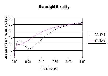
In another recent job the challenge was thermal stability of boresight among several instruments in severe environments.  I ran the complete mission profile (power dissipation, ambient temperatures, etc.) through the finite element code in thermal analysis mode.  These temperature vectors were then read into the Unified NASTRAN model (generated by my Ivory Optomechanical Modeling Tools) to calculate the boresight shift over the duration of a one-hour mission.

The good news is that Ivory-generated finite element models can provide accurate predictions for LOS and boresight in all the usual service environments.  The mechanical engineer just has to apply them early enough to claim sufficient space for the structures and other resources necessary to assure a stable system.  Too often it seems the analysis budget is committed after the mechanical design is essentially completed and a redesign becomes a financial crisis and sometimes a philosophical crisis as well.  I have found that Ivory-generated analyses often provide the engineer the credibility necessary for success in those early allocations of scarce resources in the tough projects.

Autumn is in the air here in Southern California.  I hope you all had as great a Summer as I have! 

It was good to see some of you in San Diego last month and it will be good to see others of you in San Jose come January.

Don’t forget about our conference in San Diego next August.  Get your manuscripts ready to go, the Call for Papers will be out in a couple of weeks.

Cheers! Keep the good stuff rolling.

Al H.
9/26/08

Optomechanics – Ivory: Accurate Model of Imaging Behavior

Colleagues:

An interesting, and challenging, recent job was:

“Find a way to assure a 7 microradian boresight shift
and image jitter performance specification for a mid-wave FLIR
in an airborne thermal and random vibration environment”.


The solution used the Unified Modeling mode of the Ivory Optomechanical Modeling ToolsIvory accurately modeled the imaging behavior of the FLIR and generated a NASTRAN optomechanical finite element model for the dynamic analysis. 

The model’s results were validated against Zemax environmental analyses, longhand (Excel, actually) calculations and rigid body checks in NASTRAN giving the instrument’s focal length.  (Yes, NASTRAN can calculate the focal length of on optical instrument.)  The indicated uncertainties were all less than 1.8%.

The model turned out to be a very effective design tool.  It was run more than 50 times over a few weeks.  We were able finally to demonstrate safety margins of between 25 and 1000 on the image jitter and boresight shift requirements. 

You may see some of the product from this effort in the attached “pdf” file.  My client has all of my modeling files, which are heavily annotated, so he can “mesh” his ProE solid models as they mature and replace the beam and shell elements of my early model.  Ivory’s Unified Optomechanical Model will work, of course, in any NASTRAN model he chooses to put together to check the progress of the design.

The Ivory Optomechanical Modeling Tools answered the challenge.  If you have any interest in these kinds of things, please feel free to give me a call.  I’d be happy to talk with you.

I hope you all survived Spring Break!

Al Hatheway
5-3-07

Optomechanics – Year in Review

Colleagues:

Happy Holidays!!!

We have been very busy this year: a very advanced multi-spectral sensor, an active remote optical sensor with six moving lens groups, actuators for an spacecraft assembly shop and a FLIR with stringent boresight requirements (among other joys).  I’ll try to get out more on these later.

We have also been busy incorporating NASTRAN unified modeling capabilities into Version 2.0 of our Ivory(tm) Optomechanical Modeling Tools suite of software.

As an expression of the Season’s Goodwill we will honor all purchases of Ivory2 received by January 31, 2007, by including the NASTRAN unified modeling tools and respecting our current prices.  Just the kind of offer to tickle an optomechanical engineer’s sugar-plumb dreams.

For more information on Ivory2 please open the attachment or visit our web site.

Have a Merry Christmas and a Happy New Year!

Let the good times roll.

from all us folks at Alson E. Hatheway Inc.
December 12, 2006