Optomechanics – Simulation vs Analysis

Colleagues:

Recent events have caused me to contemplate distinctions between simulation, on one hand, and analysis, on the other.

AEH was asked to determine the root-causes of a thermal shift in the back focal length of a lithographic lens.  The optical design couldn’t predict it. 

The optical, structural and thermal physics were modeled (we call it “Unified”) in a single code, MSC/Nastran.  The deviations from the actual physics (including simplifications) were noted and quantified.  Check-out results were validated against CodeV to prove their optical rigor.  The analytical results agreed well with experimental data.  Their agreement was limited by the mesh in the finite element model, which is typical in optomechanical problems, and it had been noted among the deviations.  The sources of the thermal shift became obvious in reviewing the output data.  These observables-in-the-data are called “diagnostic vectors.”

AEH calls this approach “Unified Analysis” because it keeps all the data together in a unified database, which is often one printable output file.

If your methods aren’t initially validated, if you haven’t been able to quantify the deviations between your methodology and your sciences and if you cannot trace backward from the “effect” to the “cause” then you’ll probably not recognize the diagnostic vectors, nor be able to identify the sources of problems and formulate solutions.

In the age of eye-candy simulations these practical steps often get lost.  Visuals are good but it’s the numbers, including how they’re derived and how they’re used, that counts.  That’s analysis.

When the numbers are important AEH will be there to help you.

Oh my!  School has started!  Good Luck to all the children.

Al H.
8-24-15

Optomechanics – Completing the Zemax Prescription with Ivory

Colleagues:

Well, I’m just back from a week in San Diego for SPIE’s Optics+Photonics meeting.  WOW!  Everybody seems to have some way to “model” optomechanical behavior but nobody seems to know how to verify that the results are right.  That’s why I created “Unified Modeling” (the Ivory and Ebony Optomechanical Modeling Tools):  to provide the engineer verifiable confidence in the results. 

A good friend of mine likes to declare “You need to know the answer before you do the analysis!”  Cute, huh?  It always goes over well from the back of the room during a CDR.  Well, the next-best-thing (I have found) is to have used the same procedures and theories to analyze a case (any case) for which you already know the answer.  One of my favorite test cases is called a “six degree of freedom rigid body check.”  You put the model through three translations (X, Y and Z) and three rotations (Rx, Ry and Rz).  In optical systems it’s easy to predict the image motions on the detector.  They’re either 1.0, computational zeros or some predictable fraction of the back image distance.  And, you don’t need a finite element code.  You can do it all in a spreadsheet.

AEH analyzed the stability of a hyperspectral sensor.  Our client provided the optomechanical influence functions based upon the Zemax optical design.  The random analysis showed that the image stability was out of specification by an order of magnitude.  A subsequent six degree of freedom rigid body check showed large values in stead of computational zeros.  A review of the influence functions showed that they were incomplete.  AEH put the Zemax prescription into Ivory to get a complete set of influence functions.  This six degree of freedom rigid body check showed computational zeros across the board in a spreadsheet!  And subsequent Nastran random stability analysis predicted the performance would be within specification.  Which it ultimately proved to be during qualification testing.

Unified modeling provides traceable modeling performance and helps to keep an engineer’s tools sharp.

School starts next week.  Good luck to all the children!

Al H.
8-21-15

Optomechanics – Save your Budget: Identify Problems Early

Colleagues:

How does a mechanical engineer identify problems early?  He or she runs estimates and analyses, maybe solving two or three degree of freedom (DOF) lumped-parameter problems via simultaneous equations in a spreadsheet.  Estimating surface temperatures on the outside of a cast housing comes to mind with simultaneous radiation, convection and conduction needing to be considered. 

But, throw in optical imaging behavior and the number of equations explodes.  The optomechanical engineer deals with not only the structural and thermal equation but also the 49 equations for each optical element’s effect on the system’s image.  For even modest optical systems this swamps the engineer’s conventional methods.  Who’s going to solve a 100+ equation problem in a spreadsheet?

It’s one thing to write about lumped-parameter optomechanical modeling. It’s a whole other thing to actually do it.  The optomechanical engineer needs optomechanical toolsHere’s a “relatively simple” 874 equation (DOF) optical/structural lumped-parameter model:

All of the 784 optics equations were modeled in AEH/Ivory and imported to the MSC/Nastran lumped-structural model (90 equations) for numerical solution.  The Nastran run identified critical thermal alignment challenges, the solution to which enabled a successful telecoms product.  Assembling and running simple lumped-parameter optomechanical models saves budgets, saves schedules and snatches success from the jaws of failure.  That’s engineering.

If you have questions give AEH a call.

I’ll talk more about this in San Diego at SPIE’s Optics+Photonics Symposium, come August.  We’ll have a two-day conference, poster sessions and an evening meeting of the Optomechanical Engineering Technical Group.  It’ll be a great time with technical exhibits, banquets and camaraderie.  I hope to see you all there.

Meanwhile… identify problems early, stay on top and keep your tools sharp!

Al H.
6-10-15

Optomechanics – Prepare for Success Early

Colleagues:

Optics is an art that’s just meant to work… until it doesn’t. 

The optomechanical engineer’s job is to survey the available mechanical design spaces looking for optical problems.  The engineer identifies the problems early, gets on top of them and stays on top all the way through.  MSC Software Corporation recently published a Case Study on this subject.  Here’s the link—

Optomechanics at MSC

Many problems can be anticipated and avoided by using relatively simple, lumped-parameter models in the beginning of a project.  If the project waits until the distributed properties are well defined it may be too late and the budget and schedule considerations may even shut the project down.  Optomechanical analysis is at least an order of magnitude trickier than the individual disciplines alone.  So the engineer has to have tools, and that means being able to couple the structure to the optical behavior in a single code.  AEH uses MSC/Nastran and AEH/Ivory.

Here are two examples, one a success the other a failure.  Both were gimbal-stabilized telescopes of roughly the same size:

The failure was a project that would not let the lumped parameter LOS model be run in the beginning but insisted that the analysis model be prepared from the finished engineering drawings.  The full-up analysis showed an unstable LOS.  Redesigned solutions were possible but costly. This project was cancelled. 

The successful project was able to demonstrate sufficient margin of safety with the lumped parameter LOS model that a full-up optomechanical model wasn’t needed.  The structural engineers could concentrate on strength and safety.  This project was fielded. 

Neither outcome was intuitive or obvious at the projects’ beginnings but their results couldn’t have been more stark.

Powerful tools, simple models, early in the project:  The eye-candy may be poor but the numbers can save the engineer’s buttons.

Spring is lovely in Pasadena.  I hope you’re enjoying it as much as I am.

Al H.
5-14-15

Optomechanics – Ivory and Cluster Lenses for Panoramas

Colleagues:

I’ve shared with you the tale of the errant window in a vacuum chamber where the issue with the instrument under test was less a change of the effective focal length than a change in the back focal length.  Well, here’s another tale along a similar vein.

It concerns a lens for cameras used in clusters to make large panoramic images stitched together from the smaller individual images.  The lens had to be entirely passive, no adjusting mechanisms were allowed.  They came up with an ingenious combination of glasses that would produce the required image quality as well as exactly balance out the thermal expansion of an aluminum alloy structure so as to stabilize the effective focal length over a broad range of temperatures.  In service tests the image size was perfect for stitching but the image was out of focus at the extreme temperatures.  They had assumed that the second principal plane (and therefore the back focal length) was stationary.

The situation becomes evident when the prescription is put into Ivory.  Importing Ivory’s output file into a spreadsheet permits calculation of both the focus registration sensitivity, Tzi/C°, and the image size sensitivity, DM/Mi-C°. 

Control of two dependent degrees of freedom, image size and image focus, requires two independent variables.  Only the properties of the aluminum alloy in the housing were available so only one of the variables could be “zeroed.”  The back focal length was left to float with the focus registration, TZi/C.  Rummor has it that they finally added a focus mechanism.

The Ivory Optomechanical Modeling Tools provides the engineer access to these behaviors of optical images, avoiding much embarrassment.

The all new Ivory 3.0 is now available with annotated project files, diffraction gratings, Unified Nastran modeling and much, much more.

And just in time for Valentine’s day!

Al H.
2-5-15

Optomechanics – The Calibrated Thumb Technique

Colleagues:

One of my early bosses, Wilford, introduced me to the “calibrated thumb” technique.  The immediate challenge was to anticipate static deflections and resonant frequencies in new design work.  His broader purpose was (I have since come to think) to open my mind about ways to develop my estimating skills.  I was working in airborne IR countermeasures at the time. 

I’ll introduce the technique to you with a much more recent example. 

I had been called in to make dynamic boresight stability analyses for a multi-sensor suite.  It was presented to me as an all-up finite element solid model of the system with three million-plus degrees of freedom.  I incorporated Ivory’s optomechanical constraint equations to calculate the line-of-sight errors for each sensor and the boresight errors between them.  This unified optomechanical model passed the rigid-body checks and static gravity checks just fine.  The calculated boresight errors were small compared to the specification. 

But I had an uneasiness.  There are lots of places in complex models to enter typos, select the wrong property from a long list or drop some decimal places.  How can I settle my uneasiness about someone else’s model?  My client had been around a while and done a lot of good stuff in the past, so I got an idea.

I went out to their shop where a variety of similar sensor systems were sitting on granite surface plates.  I got a height gage with a digital indicator and set it next to one of the systems.  Then I pushed on the system with my thumb applying what I thought to be about 1.0 pound and observed the deflection under the digital indicator’s tip.  I repeated it with two other sets of hardware in the shop.  The deflections were all somewhat different.  That was expected since the systems were of substantially different sizes.  But they’d all been designed and built by this organization.

Then I did a thought experiment, “If I push on the unified model with my thumb how much deflection should I expect?”

I went back to my computer and applied a similar load to the model.  The computed response compared well to my thought experiment.  My anxiety eased and the model proved, in test, to be reasonably accurate.  Whew!

A calibrated thumb is a good thing to have.  Thanks, Wilford.

Of course, my calibrated thumb is one of the tools I try to keep sharp.  When I got back to my home office I checked my thumb with a postal package scale.

Use it or loose it!

Al H.
1-29-15

Optomechanics – Early Adoption Matters

Colleagues:

At AEH we study closely the ways things fail.

It is often said that an engineer’s job is to make things work.  Well, that’s nice.  Tinkerers can do that too.  What’s really required from engineers is to make things work every time.  That’s a little different discipline. 

So, as engineers AEH studies how things fail in order to better know how to prevent bad things from happening:

In optical systems, virtually all “optical” failures result from some defect in the mechanical implementation.  These failures are never corrected by changing the optical prescription.  Well, almost never:  There was the Hubbell primary mirror fix.

Optomechanical problems are best spotted early, while the design resources (size, shape, mass, arrangement, interfaces, etc.) are malleable.  Those resources can quickly become depleted, even unavailable, as they are claimed by other interests:  bearings, servos, electronics, cryogenics, subcontractors, etc.

Early detection requires special tools for the optomechanical engineer.  To assess optomechanical problems the optics and mechanics must be coupled by the engineer, hopefully from the first publication of the prescription, perhaps during the proposal effort even. 

The results of this early optomechanical coupling may only be estimates, but they’re essential.  They give the engineer who uses them a sense of how to guide the design to his desired…, no, to his required destination: 

Spot-on performance with a trouble-free service life.

Early assessment of optomechanical problems is one way we help our clients.  AEH has the tools:  longhand, ten-key, spreadsheet and Nastran. We’ve got all that plus Ivory, Ebony and Jade to interpret the optomechanics for you.

Of course, we can often help after problems materialize and the corrective options have become more restricted.

Joy to all for the Autumn season.  It has arrived!

Al H.
10-6-14

Optomechanics – How to Design with Ivory

Colleagues:

When performance is crucial the engineer uses tools to assure it.  Let me show you:

Say, we need a hyperspectral design with a 60 cm entrance pupil and stabilized to less than 15 ur, rms, LOS error in object-space.  We have the physical prescription.  How to get started?

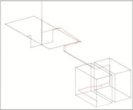
The first thing I do is run the physical prescription data through AEH/Ivory Optomechanical Modeling Tools and import them into MSC/Patran-Nastran to start a system model (1).  The pink lines represent the optics and the yellow lines are structural bar elements with lumped masses. 

It’s a crummy “visual” but a very important first step.  I validate the model with rigid-body checks.  Then I run the model through random vibration adjusting the properties of the bar elements (areas, inertias, materials, etc.) until AEH/Ivory-in-Nastran satisfies the LOS performance requirement (12.3 ur, rms, in this case) with a reasonable combination of properties.

(1) 12.3 ur, rms
(2) 12.8 ur, rms
(3) 11.9 ur,rms
(4) 12.7 ur, rms

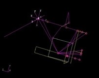
Next I incorporate solid models of the optical elements and replace the simple bars with more complicated beam elements (rectangular and circular tubes, some tapered) and optimize their wall thicknesses to maintain the AEH/Ivory-in-Nastran LOS performance (2).  I now have an estimate of a housing geometry (masses, dimensions, thicknesses) that will meet the LOS performance. 

The CAD engineer has decided on a three-piece housing design; an objective, a compound elbow and a detector.  The first section we develop is the compound elbow that holds the grating.  The CAD engineer makes a model which I import into the system model.  When we have an elbow design that maintains the AEH/Ivory-in-Nastran LOS performance in the system model, (3), we move ahead.

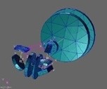
We design the objective and the detector sections next, import them, one at a time, into the system model.  We run the model through random vibration adjusting properties to maintain the AEH/Ivory-in-Nastran LOS performance before proceeding.  Finally, (4), we have developed a three-piece optical housing design through an iterative engineering process that supports the required LOS stability.

That’s optomechanical engineering with tools.  No surprises.  No excitement.  Just getting where we need to go, working from the optical prescription.

Now, to play a little…

Oh!  Joyous Summertime.

Al H.
7-7-14

Optomechanics – Preventing Failure

Colleagues:

As an engineer I’m absorbed with understanding the ways that things fail.

It is often said that an engineer’s job is to make things work.  Well, that’s nice.  Tinkerers can do that too.  The fact is that success rarely rewards an engineer while a single failure can nearly ruin him.  What’s really needed from an engineer is to make things work every time.  That’s a little different discipline.

Just ask Ray DeGiorgio, the GM engineer who’s taking the fall for the Chevy Cobalt ignition switch problem; or de Haviland, which nearly aborted the jet age, when a number of it’s Comet model passenger transports very quietly disappeared from the sky, without a trace; or the engineer who messed up the metrology on the Hubbell primary mirror.

So, as an engineer, I study how things fail in order to know how to prevent bad things from happening.

One key to failure prevention is early detection of possible failure modes.  In optical systems, virtually all optical failures result from some defect in the mechanical implementation.  These problems are never corrected by changing the optical prescription.  (Well, almost never:  There was the Hubbell primary mirror fix.)

Early detection requires special tools for the engineer.  To detect optical problems the optics and the mechanics must be coupled by the engineer from the moment of conception.  The results of this early coupling may only be estimates, but they’re essential.  Few early engineering estimates provide elegant eye-candy, and to some people they may not be persuasive.  But they give the engineer a sense of how to guide the design to the desired…, no, to the required destination.  The estimates will be refined and formalized as the design matures and eventually may become deliverable analyses.

The tools the engineer uses must be able to grow with the project from early conceptual estimates to the final NASA, DOD or NTSB reports, a continuous flow of engineering evaluations using the same proven techniques with demonstrable quality within a growing database of design detail as the project progresses.

That’s AEH’s mission and that’s why I study the way things fail. 

And that’s why I’m going to have a terrific Summertime!

How about you?

Al H.
6-27-14

Optomechanics – Preventing Boresight Errors

Colleagues:

If engineering can be said to have a “purpose” it might be “to survey the available design spaces and guide the design process to avoid future failures.” 

An especially tricky aspect of optomechanical engineering is avoiding unacceptable boresight errors among instruments during thermal transients.

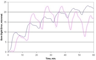
One example is a target designator that was required to operate on a 50% duty cycle with a maximum on-time of five minutes.  The boresight was important because the laser and the imager operated in different bands so the operator would not be able to “see” the laser spot in the FOV.  The boresight error was required to be less than 15 microradians over one hour of operation.  As shown in the figures the maximum boresight error was predicted to be 12 microradians after about 54 minutes (blue is the laser and pink is the imager).

In order to achieve acceptable stability it had been necessary to add some bracing between the laser beam expander and the imager’s primary mirror.  Adjustments in the position of the laser had also been necessary.  These changes were made early enough in the design process to avoid a major disruption of the program. 

AEH/Ivory Optomechanical Modeling Tools provided the critical link required to assure the system’s optical performance.

Baltimore was glorious and I had a great group of students.  But it’s good to be home!

Enjoy the fresh Springtime.

Al H.
5-27-14