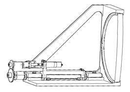
I am now in receipt of a genuine photograph of a genuine failure of a glass lens in a metal ring mount. It was in a laser cavity and failed (fractured) during high rep-rate operation. The engineer avers that “there may also [have been] some stress concentration in the mount such as a burr or particle” but he feels they solved the problem by replacing the clamping ring with a fillet of adhesive. Good show!
I pass this along to you because I know there have to be problems out there with ring-mounted glass lens assemblies. I was beginning to think no one was reading my correspondence (and that hurt my feelings!). Now that I feel better, I’ll stay out of your mailboxes for a while.
I also want to honor the engineer who sent this example in. Broken glass is not pretty and sometimes it takes courage to talk or write about it.
Some of you may remember a survey I conducted a couple of years ago concerning
the fracture of ring-mounted glass lenses. Of the 300 or so optical
professionals queried (OSSC and SPIE members, mostly) not one had first-hand
experience in such a mounting failure. Several expressed grave concern
and one or two had heard stories that they felt were creditable. This
group must have personally guided thousands of lens mount designs. And
not a single fractured lens among them. This basically validated my
experience: I’ve never had a ring-mounted glass lens fracture because of
its mounting.
The anomaly here was that the accepted structural theory (Delgado and Hallinan,
Opt. Eng. 14, S11, 1975) predicted very high tensile stresses in the lenses,
especially at low temperatures when the metal contracts more than the
glass. Many failures should have been reported, especially in the
military sector where low temperature operation is required.
The good news is that the accepted structural theory was wrong. Those
authors accepted that the contact between a sphere and a flat plane is the same
as the contact between a ring and a flat plane. The stresses in the
sphere-on-plane case had been solved by others whereas the stresses in the ring-on-plane
case would take some additional development effort.
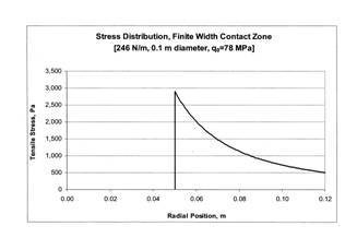
Now, the ring-on-plane case has been solved (Hatheway, Proceedings of SPIE,
7424-14, 2009) for the surface tensile stresses that may cause fracture.
For comparison lets take a lens cell I designed a short while ago. The
lens is 10 cm diameter and needs a ring compression load of 77.3 N to secure it
against a shock load of 20 gs.
The peak tensile stress according to the sphere-on-plane theory is
s=15,300,000 Pa (2,238
psi)
(Delgado and Hallinan)
and the peak tensile stress for the ring-on-plane theory is
s=2,893 Pa (0.422
psi)
(Hatheway)
a ratio of 5,300:1, almost four orders of magnitude. The higher level
(2,238 psi) is enough to cause fracture in a short period of time (about three
minutes). The lower level (0.422 psi) would provide a lifetime longer
than the engineer who designed it (10.3 x 10¹⁴ years) and possibly
account for the lack of witnesses in my survey, above.
Those of you interested in the gory details can download my paper from the SPIE
website. Please don’t ask me for copies because I’ve signed the copyright
over to SPIE. However, as a consolation prize for reading this email all
the way through I’ll give you the answer:
Peak tensile stress=P(1-2u)/2pr2
where P=ring loading (dimensions of force), u=Poisson’s ratio
(dimensionless) and r=radius of the ring contact (dimensions of length).
Well, Summer was very mild in Southern California until the fire season broke
out, in spades. It looks like we’ll make it through this spate OK
but that season is just beginning for us.
Here’s wishing us all a terrific Autumn and getting the little ones back to
school. And here’s to all that broken glass that didn’t happen, this
time.
That is a question I’ve asked my students ever since I started teaching a class on optomechanical tolerancing of instruments, ca. 1990. It’s amazing, the answers I’ve gotten.
It recurred again recently with a client who had a contract to produce a number of ultra-wide field imaging instruments. The lens was composed of 19 glass elements arranged in nine singlets, four cemented doublets and two cemented triplets. The optical prescription was supplied by their customer as were the allowable alignment tolerances: ±0.005 mm in Tx, Ty and Tz and 20 arc-sec in Rx and Ry.
First, we had to establish the accuracy of their in-house fabrication processes. Getting the crib-notes out of the technicians was real sport. Then we had to find out the accuracy of their suppliers. The latter is usually much more problematic since you don’t really find out anything until you try to negotiate a contract (or, worst-case, only when the parts are delivered). Finally, we had to incorporate alignment mechanisms to make up the deficits, whatever we thought they may be.
You can put it all in a spreadsheet and have great fun with it!
Also back in the ’90s, I was asked by one of the shakers-‘n’-movers in the
optical industry if I would publish a summary of the state-of-the-art of
achievable manufacturing accuracy for the various manufacturing
processes. It would be a great boon to the industry, he said, and indeed
it would. Unfortunately, manufacturing accuracy is not a fixed quantity.
Not only does it vary over time but also with geography, supplier and price
(not to mention attitude). And the variation with each of these is not
always favorable.
In the above example one of my client’s suppliers (actually, their preferred
machine shop) refused to adopt innovative techniques that could provide the
required accuracy, presumably because they had committed to a price before they
knew what was to be demanded of them. Or maybe they didn’t have the
confidence in the precision of their machine tools that I expected. Or
maybe they had too much work and this would disrupt their shop practices.
Who knows?
So, back to the spreadsheet and more fun! Thumb the yellow pages and
buyers’ guides. Explore changes to the construction materials.
Re-tolerance the optics? Call the customer? In some ways good
engineering resembles good accounting; keep pushing the numbers around until
you find a workable combination.
That’s engineering, and one more amazing
answer to that question.
I have recently been involved in lively discussions about the nature of glass as a structural material and how to predict its strength properties. The fact is that glass is by nature one of the strongest materials on earth with a “native” tensile strength on the order of 500,000 psi, stronger than most high alloy tool steels. So, I am asked, “Why do the glass suppliers say to keep the stresses under 1,000 psi?” The answer is that, unlike steel, glass is completely brittle showing no perceptible plastic deformationwhatever in it its fracture.
The growth of cracks in stressed steel parts is arrested by the plastic deformations in the material at the tips of the cracks. The plastic deformations produce a small radius at the tip of an otherwise sharp crack, thereby reducing the high concentrated stresses (by orders of magnitude) at the very tip of the crack.
The growth of cracks in stressed glass parts is not arrested since plastic deformation does not occur. This does not mean however that the strength of glass is indeterminate, unknowable or a random property. It does mean that you should expect that glass has slightly different behavior than the ductile structural materials like steel.
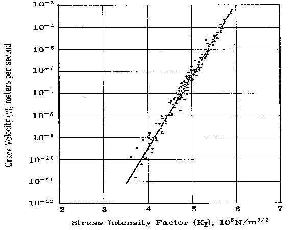
It has been shown by a number of researchers that under tensile stress a crack in glass will tend to grow in length (or depth) at a rate that is proportional to the nominal stress at the tip, s, and proportional to the square-root of its length, d. To quantify the influences of stress and crack length on strength properties, structural engineers have developed a quantity known as the “stress intensity” that is usually represented by the character “K1.” K1 includes a coefficient, a, that accounts for the geometric shape of the crack and is defined as,
K1 = s(ad)^.5
A crack propagation curve for fused silica is shown in the figure.
Other glasses may have different, even zig-zag, curve shapes.
It has also been shown by researchers that the crack will continue to grow in this predictable fashion until the stress intensity reaches a critical value, K1c, at which point the crack growth becomes unstable and proceeds rapidly to complete fracture without a velocity limit (except, perhaps, the speed of sound in the glass). The critical stress intensity, K1c, is often published as the material strength property for a glass, ignoring the propagation effects above.
Glasses, especially optical glasses melted and cooled in a boule, are very uniform, isotropic and crack-free in their as-cooled state. They exhibit the high “native” strength described above. The cracks we are talking about here are all produced in subsequent fabrication processes: single point turning, grinding, polishing, etc., all of which produce sub-surface cracks that are about three time as deep as the diameter of the abrasive used in the process. Polishing may remove visible grinding pits that are about as deep as the abrasive but may also leave behind invisible subsurface cracks that can still be twice as deep as the abrasive grinding grit. “Controlled grinding and polishing” is the art of reducing and/or minimizing these residual subsurface cracks by special fabrication techniques.
So, this is the physics: Ground and polished glass parts with structural stresses in them all have finite service lives because the cracks will grow continuously until complete fracture. The lower the stress, the longer the life will be. At 1,000 psi and with common optical finishing processes, the parts life may approach the human life span, sufficient for most cases and often recommended by glass suppliers.
As an engineer it is my practice, at higher stress levels, to integrate under the crack propagation curve to determine the acceptable fabricated crack length, d, in a glass part exposed to a known stress history and with a required service life. The lower limit of integration is the stress intensity, K1i, at the initial as-fabricated crack length and the upper limit is the critical stress intensity, K1c. This calculation provides the user with an assured minimum lifetime for his product. It also lends itself to definition of non-destructive proof-testing for finished products to demonstrate the safe service life of each one.
I perform the integration in custom software that I call Crystal. Crystal accommodates arbitrarily-shaped propagation curves and time-varying loading.
One “snag” is that glass producers have not been encouraged to publish crack propagation curves for their glasses so the data are fairly sparse. On the up-side however there is sufficient published data that a safe envelope for similar types of glass may often be assumed.
So, this is the engineering: respect the physics and avoid broken glass.
Now… Springtime is here and the snows will melt. Yes, even in Spokane and Burlington!
I recently completed a job as an advisor to an airborne multi-spectral sensor system project. My tasks included advice on lens mounting (metal rings vs. adhesive bonding), environmental sensitivities (temperature, vibration and shock), alignment procedures (tooling and adjustments) and manufacturing processes (bonding, glass finishing and failure analysis).
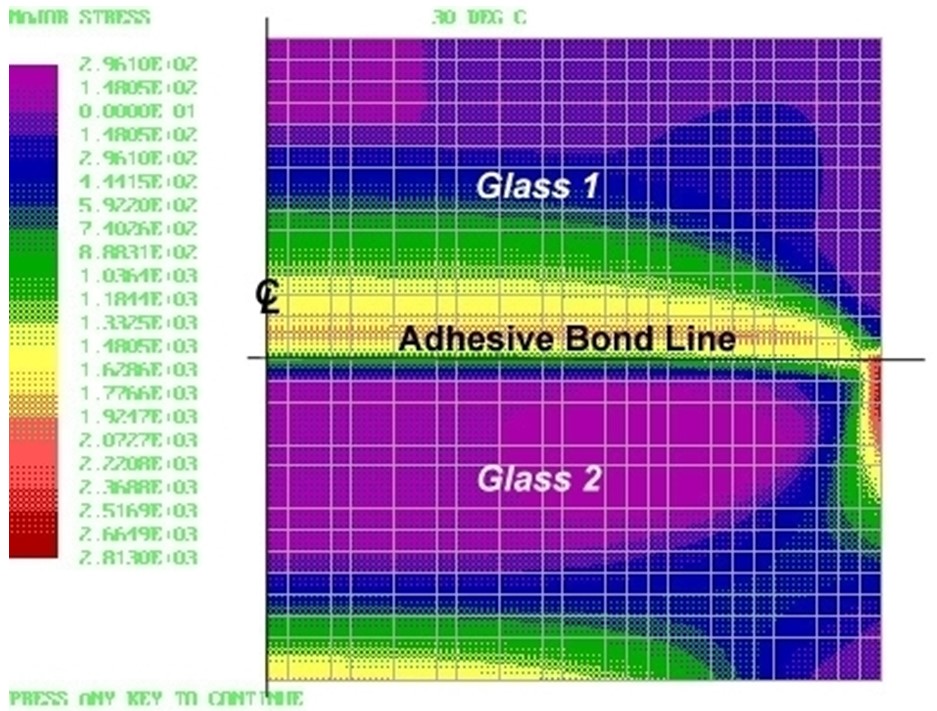
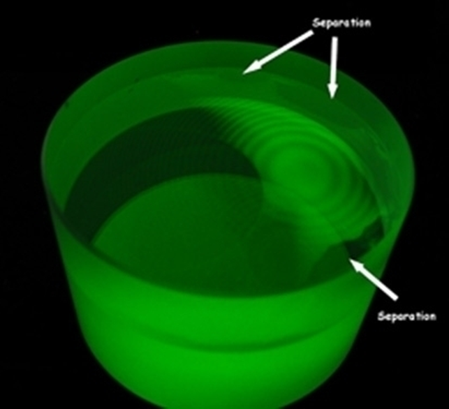
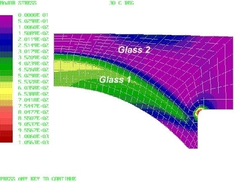
A major concern was the fracture of cemented lenses at high and low temperatures. Understanding the physics of glass fracture was instrumental in both understanding the causes of the fractures of cemented assemblies and designing them to avoiding failures in the service environment. The figures below show the analysis and test of a cemented glass coupon. The contour plot shows the stress distribution in the test coupon and the photo shows the resulting de-lamination and fracture at low temperature.
In one of the finished cemented doublets, analyzed below, the fillet in Glass 2 needed special finishing to strengthen it against the stresses at low temperature.
This project was very challenging. Great sport!
I hope your summertime was as interesting as mine.