Optomechanics – Ivory and Cluster Lenses for Panoramas

Colleagues:

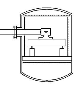
I’ve shared with you the tale of the errant window in a vacuum chamber where the issue with the instrument under test was less a change of the effective focal length than a change in the back focal length.  Well, here’s another tale along a similar vein.

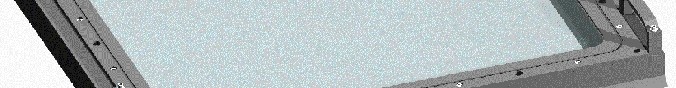
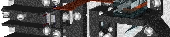
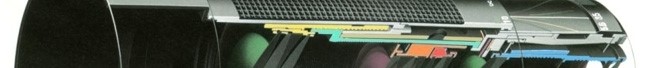
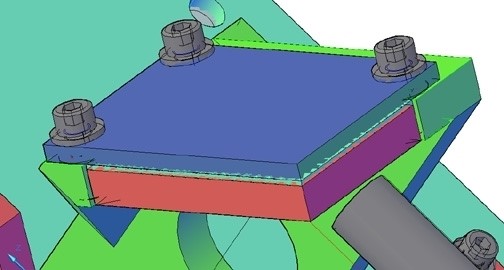
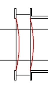
It concerns a lens for cameras used in clusters to make large panoramic images stitched together from the smaller individual images.  The lens had to be entirely passive, no adjusting mechanisms were allowed.  They came up with an ingenious combination of glasses that would produce the required image quality as well as exactly balance out the thermal expansion of an aluminum alloy structure so as to stabilize the effective focal length over a broad range of temperatures.  In service tests the image size was perfect for stitching but the image was out of focus at the extreme temperatures.  They had assumed that the second principal plane (and therefore the back focal length) was stationary.

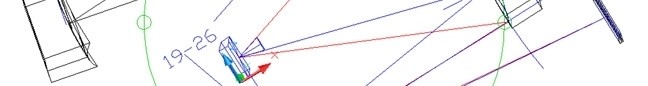
The situation becomes evident when the prescription is put into Ivory.  Importing Ivory’s output file into a spreadsheet permits calculation of both the focus registration sensitivity, Tzi/C°, and the image size sensitivity, DM/Mi-C°. 

Control of two dependent degrees of freedom, image size and image focus, requires two independent variables.  Only the properties of the aluminum alloy in the housing were available so only one of the variables could be “zeroed.”  The back focal length was left to float with the focus registration, TZi/C.  Rummor has it that they finally added a focus mechanism.

The Ivory Optomechanical Modeling Tools provides the engineer access to these behaviors of optical images, avoiding much embarrassment.

The all new Ivory 3.0 is now available with annotated project files, diffraction gratings, Unified Nastran modeling and much, much more.

And just in time for Valentine’s day!

Al H.
2-5-15

Optomechanics – What do Optomechanics do all day?

Colleagues:

What does the optomechanical engineer bring to the table?  Hmmm…

A  few months ago a structural engineer friend asked me to analyze the strength of a lens assembly that he didn’t feel comfortable with.  It was injection-molded plastic, elastomeric rubber and glass.  OK…

Before that an optics friend challenged me to explain why it might be OK to mount glass lenses between threaded aluminum rings.  So, I did, but it took a while…

Another optics friend got me involved in resolving intellectual property disputes for mechanisms in cinematography lens assemblies…

Then a mechanical engineer friend needed a mass properties trade-off study between BK7 and sapphire for an airborne surveillance window…

Then another optics friend inquired about the possibility of nanometer-class structural actuators for 30 degrees K space optics.  So I designed, built and tested a successful set of them…

And before that I was asked to rationalize the structural damping coefficients to be used in an optical image jitter analysis.

The optomechanical engineer thinks outside the box.  He needs to work outside the box as well. 

Actually, I got that backwards:  He needs to work outside the box in order to be able to think outside the box.  It’s the peculiar demands, outside of his art, placed on the mechanical engineer by optics that inspire in him the intellectual curiosity to find workable engineering solutions.

Besides, he gets to enjoy your occasional company, too.  Thank you.

And, don’t forget to submit your abstract for “Optomechanical Engineering 2015.”
Assure your position in the program now:
         http://spie.org/OPO/conferencedetails/optomechanics
Hmmm… which one should I submit? 

Al H.
12-1-14

Optomechanics – How the Instrument Might Fail

Dear Colleagues:

I had a terrific group of students for my class, “Optomechanical Analysis,” at Photonics West.  It was a generous mix of the disciplines that support the optical industry.

One of the things I teach is how I calculate the ways in which the nearly-a-myriad mechanical design variables can affect the performance of an optical instrument.  A simple example I use is the net effect of tolerances on the position, orientation and size of the image.  The tolerances I address include those on the optical elements themselves.  This allows the engineering team to balance the mechanical tolerances and the optical tolerances.   I take the sum of the absolute values of the effects of the individual design tolerances. 

I am usually challenged by at least one of the students that the root-sum-square of the effects gives a more reasonable value for an assembled instrument.  I respond that as optical instrument designers they are right.  But, I add, as a mechanical engineer I’m also concerned about how the instrument might fail and that the sum of the absolute values gives me better insight into that eventuality, ie., how it might fail in the assembly and alignment process.  I have found that insight very valuable.  The analysis not only alerts me to possible worst-case scenarios it identifies the major contributors to the problems and suggests available corrective actions. 

All in a day’s work.

Ciao, from Baghdad by the Bay.

There will be more, but after Valentine’s Day.

Al H.
2-7-13

Optomechanics – Zero Chance for Failure Over 15 Years

Dear Colleagues:

I had one terrific Summer.  I hope you enjoyed it as much as I did.

One highlight of the Season was the analysis of a meter-class optical window to assure safe operation over a 15 year service life in transport-type aircraft.  Safe means zero chance for failure over 15 years (no Weibul statistics for these folks!).  Fortunately, they had selected a glass for which there is good engineering data, i.e. the fracture toughness, the crack propagation rates and the stress-corrosion effects of moisture had been well defined and quantified.  My job was to define the proof test for the new windows that would assure the product safety for 15 years and another proof test to be used at the periodic reinspections.

The procedure is a deterministic one.  The engineer integrates the crack propagation velocity repeatedly over the time of the stress transient until the crack grows to critical size at which time complete fracture occurs instantaneously.  I use MSC/Nastran finite element code to define the stress transient and I use AEH/Jade brittle fracture software to perform the numerical integration.  AEH/Jade allows me to easily vary the initial crack size and the integration time step.  The latter allows me to demonstrate convergence in the time domain which may be very important in complicated stress transients.

Once an acceptable initial crack size has been determined the defining proof test becomes a piece of cake.

Well, that was one of this Summer’s adrenalin highs.

I’m sorry for having been away so long, but I was having way too much fun!  More later, I promise.

Look out!  All Hallow’s Eve awaits you.

Al H.
9-24-12

Optomechanics – A Collaborative Art

Colleagues:

Optomechanical engineering is a collaborative art, a fascinating blend of optics, machine design, structural mechanics, servo controls and heat transfer.  I tend to emphasize my (mechanical) contributions in these missives.  But enough about me.  This time I want you guys to stand up and take the bow.  Let’s list at a few topics from the recent past:

Membrane optics research (of 2-28-12)
My contribution of designing some test facilities and helping with the tests was nothing compared to the conception of the telescope it was intended to support.  My thanks to the telescope designer, the lab technicians who ran the tests and the structural engineers who interpreted the results.  (Applause)

Tensile stresses in ring mounted glass lenses (of 8-31-09)
A dear friend and colleague persisted in his belief that glass was too fragile to be mounted in metal rings.  A survey of the literature showed no solution for this load condition and the nearest ones, point load and line load, were unreasonable.  So, I got out my pencil (remember those?) and developed the solution for ring loading.  My thanks to my dear friend.  (More applause)

Mounting mirrors with elastomers (of 2-6-12)
The optics community has been searching for the perfect “athermal” mounting scheme for years.  Guess what, there isn’t one.  This is one of my contributions to the lore.  Love (and Timoshenko) made me do it.  My thanks (posthumously) to Alexander and Stephen.  (More applause)

Stabilizing lines of sight (of 7-12-11)
I teased the servo engineers, the structural engineers and the “optikers” somewhat mercilessly.  It was entirely rhetorical.  They were the heroes of the story.  No one gets down to microradian stability levels on moving earth-bound vehicles unless they all have done a very good job.  My thanks to the servo engineers, structural engineers and “optikers.”  (Still more applause)

Co-inventing a remote sensor (of 4-17-12)
An optical designer friend thought my nanometer-class structural actuators with his lens design skills would be the solution.  He was wrong.  The best approach was an entirely optical solution, with his lens design skills and somewhat more complicated optics.  It worked.  And I got to do the mechanical design!  My thanks to my optical designer friend.  (And yet more applause)

My list is nearly endless.  And each of you has been a stimulus, a catalyst and a joy to have as a friend and a colleague.

Now, all of you, step forward and take a bow (or two or three).  (Deafening applause)

Thank you all for allowing me to participate in your adventures.

Rejoice on our Independence Day.

And happy Summertime to all.

Al H.
6-28-12

Optomechanics – Just what is it you do?

Dear Colleagues:

It’s been busy the last few months.  Some of you have asked, “Just what is it you do?”  Well, here’s just a sampling:

I’ve researched the intellectual property of mechanisms for focus and diaphragm control in camera lenses;

I’ve analyzed microradian-level image jitter in an off-axis imaging spectrometer (with AEH/Ivory and MSC/Nastran of course);

I’ve co-invented a remote sensing 10:1 zoom system with five moving lens groups, three of which are lenslet arrays.

Who could possibly have more fun than a mechanical engineer in this optics industry?

I hope you will join me in this paean to Springtime.  Joy!

Al H.
4-17-12

Optomechanics – Elastomeric Mounting of Mirrors

Colleagues:

Please allow me to complete the discussion of my engineering tool for elastomeric mounting of mirrors.

So, according to my previous missive, the elastomer reduces the shear stresses on the back face of the mirror by two to three orders of magnitude compared to a rigid adhesive.  That’s all well-and-good but how do we know that it’s good enough?  Of course those of you who have picked up the source reference (SPIE: 6665-03, 2007) know the answer.  You also know why there are no dimensional quantities (inches, millimeters, etc.) for the mirror in my equation,

In the derivation I assumed that the gravitational sag of the mirror was a reasonable budget for the figure errors induced by the mounting method.  When I equated the deflection of the mirror due to gravity to the deflection of the mirror due to the thermally induced shear stresses on the back of the mirror the mirror’s dimensions (thickness and edge length) dropped out leaving only the adhesive’s thickness, t, the environmental temperature change, DT, the difference in coefficient of thermal expansion between the mirror and the mount,   Da , the modulus of rigidity (shear modulus) of the elastomer, G, and the specific weight of the mirror substrate, sVoila!


So, that’s my engineering tool.  But plugging numbers in is the easy part.  Now the engineer has to go to work.  You’ll find a discussion of the engineering considerations in the source reference also.

Thank you for your patience. 

‘Tis mid-winter and Valentine’s day is nigh.  Ah, the joy of good company!  Thank you all, again. 

Yes Tiny Tim, thank you too.

Al H.
2-6-12

Optomechanics – Adhesive Mounting of Mirrors

Colleagues:

Let me revisit my engineering tool for adhesive mounting of mirrors:

Those of you who have studied the source reference (SPIE: 6665-03, 2007) know now that it guides the engineer to elastomeric adhesives for the mounting.  The reason for this is that hard adhesives have a high modulus of rigildity, G. This fact leads to large optical distortions of the mirror surface due to differential thermal expansion and contraction between the mirror and the mount.  But, for elastomers their low modulus of rigidity tends to isolate the mirror from the differential expansion and contraction of the mount.  The reduction in surface distortion may be a factor of between two to three orders of magnitude using an elastomer compared to a hard adhesive.

Simultaneously, Poisson stiffening tends to stabilize the position of the mirror’s surface.  It increases, by a similar factor of 100 to 1,000, the apparent tension/compression modulus, K‘, of the elastomer between the mirror and the mount (comparing K’ to the Young’s modulus, E).  The bulk modulus, K, for a silicone elastomer is typically in the range of 150,000 psi to 200,000 psi whereas its modulus of rigidity may be as low as 180 psi to 200 psi.  In thin adhesive layers the apparent tension/compression modulus, K’, approaches the bulk modulus, K.  Since the Young’s modulus would be about 570 psi, which becomes a Stiffening Factor of about 300 (see above).  The low modulus of rigidity assures small shear stresses in the bondline due to thermal expansion and contraction while the high bulk modulus stabilizes the mirror’s surface in the optical path.

Perhaps you begin to see why this tool is really not a rule-of-thumb.  It is an engineering technique for tailoring the thickness, t, of a specific elastomeric adhesive, G, to the properties of the mirror, the properties of the mount and the thermal environment the assembly will see in service.  It also requires the engineer have some understanding of the Poisson stiffening effect in thin bondlines.

I hope the Holidays left you all refreshed and eager for the New Year.  Here we go again!

Al H.
1-10-12

Optomechanics – Minimum Adhesive Thickness

Colleagues:

Wherever I visit, rules-of-thumb are a hot button topic these days.  My normal response has been that engineers are expected to do better than use rules-of-thumb.  But Fall is here and the Holidays are close-at-hand, so allow me to be a little more responsive this time. 

I develop engineering tools and skills to support and guide my engineering interests.  For instance, I have developed techniques to analyze the surface figure errors introduced by element mounting techniques.  In the spirit of the coming Season, I will give to one and all (yes, even to Tiny Tim) one of my engineering tools:

It tells the engineer the minimum adhesive thickness necessary to limit the thermal distortion of a mounted mirror.  It is easier to use than a finite element code and probably more accurate.

I do not, myself, consider the above expression a rule-of-thumb but rather one of several engineering tools for use in these kinds of problems.  The curious may read my original paper, SPIE: 6665-03, 2007.  The expression is formed by substituting equation (6) into equation (10), both from the subject paper.  I hope you find it as useful as I have.  It’s about as close as I get to a rule-of-thumb in my practice.

Now, let us turn to the approaching Season:  The Joyous, Tumultuous, Boisterous, Extravagant Holiday Season from All-Hallows Eve to Twelfth-Night.

We can talk about engineering tools, and rules-of-thumb, any old time.

We should Enjoy and take Cheer Now!

Al H.
10-24-11

Optomechanics – Flat Surfaces

Colleagues:

This is a tale about the power of flats.

The IR sensor was out of focus and I drew the straw that said, “Measure the contraction in the focal plane support structure between room temperature and 80 K.”  Others drew different straws and the project turned itself inside-out to discover the root cause of the focus problem.  This system did not have an on-orbit focus control mechanism.  (Now, now!  I hear you clucking your tongues.  But, do you know how many successful systems do not have focus controls?  Enough!  It’s my story!)

Finally, the various straw-drawers were convened and none could find a millimeter of focus error, anywhere, adding up all our contributions.  After the meeting I was assigned to another project, as happens in large firms.  I eventually left the firm not knowing how the problem was resolved.

Some time later, at an Optical Society meeting, I was sitting with one of my erstwhile compatriots reminiscing.  He declared that the problem had been resolved and was not a design problem at all, just an unfortunate artifact of the test setup. 

The germanium window in the vacuum tank sagged under the influence of the outside pressure (see the figure).  The resulting curvature of the surfaces created a meniscus lens with a small optical power ( about -5.E-08 diopters) but enough to cause the image to fall behind the focal plane by over a millimeter and send the project team into its flurry.

It’s a simple thing to check:  One equation from Roark for the deflection; a little geometry for the radius of curvature; the basic lens equation for the focal length and Ivory (or Zemax or CodeV or Oslo if you insist) for the focus error.  This firm was one of the old-line firms of Southern California aerospace and they were in space before I was out of college.  This was not their maiden voyage to low earth orbit. 

My compatriot’s uncritical views were colored (in my judgement) by his philosophical training as an optical designer.  As an engineer I was more jaundiced:  The engineer who designed the test should have seen this one coming and accommodated it (defocus the collimator, introduce a corrector lens, something).  But, it just got lost among the various groups who participated in the project.

My advice to optomechanical engineers:  Beware of flat optical elements; windows, wave plates, fold mirrors, etc.  Everyone, I mean everyone, is checking the components with any optical power.  The un-powered flat components get short shrift.  The results are often not seen until very late in the program and then they raise Holy Havoc with the engineer’s evenings and weekends.

I pass this anecdote along to you partly as a cautionary tale and partly as a celebration of the insight I gained from that compatriot one evening over a pleasant dinner at an Optical Society meeting.  That insight, pay extra attention to all the “flat” elements, has saved my buttons many times over the years since I left my former firm, uncertain about the sensor that didn’t focus.  Thanks, Bob.

The Holidays are coming and I hope you all enjoy a festive Season filled with friends, family and warm camaraderie.

Al Hatheway
11-16-10