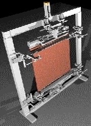
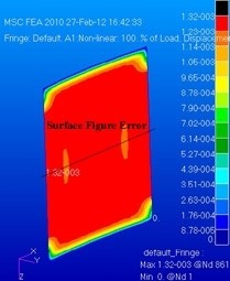
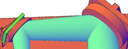
AEH tested, with a client, the ability of metal foils and polymer films to form
membranes with optically useful surfaces such as cylindrical conic sections
(SPIE: 5494-50, 2004). AEH subsequently explored the concept using
non-linear structural solution sequences in MSC/Nastran.
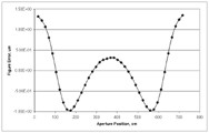
AEH’s study identifies trade-offs among the material properties, dimensional properties, initial conditions and loading. It also provides the optomechanical engineer design tools to minimize the surface figure errors in real, non-idealized, clear apertures. For instance, compensate for defects in the membrane such as non-uniform thickness, variable properties and non-planar initial membrane shapes.
AEH: Cutting-edge engineering for cutting-edge systems.
Please allow me to complete the discussion of my engineering tool for
elastomeric mounting of mirrors.
So, according to my previous missive, the elastomer reduces the shear stresses
on the back face of the mirror by two to three orders of magnitude compared to
a rigid adhesive. That’s all well-and-good but how do we know that it’s
good enough? Of course those of you who have picked up the source
reference (SPIE: 6665-03, 2007) know the answer. You also know why there
are no dimensional quantities (inches, millimeters, etc.) for the mirror in my
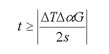
equation,
In the derivation I assumed that the gravitational sag of the mirror was a reasonable budget for the figure errors induced by the mounting method. When I equated the deflection of the mirror due to gravity to the deflection of the mirror due to the thermally induced shear stresses on the back of the mirror the mirror’s dimensions (thickness and edge length) dropped out leaving only the adhesive’s thickness, t, the environmental temperature change, DT, the difference in coefficient of thermal expansion between the mirror and the mount, Da , the modulus of rigidity (shear modulus) of the elastomer, G, and the specific weight of the mirror substrate, s. Voila!
So, that’s my engineering tool. But plugging numbers in is the easy part. Now the engineer has to go to work. You’ll find a discussion of the engineering considerations in the source reference also.
Thank you for your patience.
‘Tis mid-winter and Valentine’s day is nigh. Ah, the joy of good company! Thank you all, again.
Let me revisit my engineering tool for adhesive mounting of mirrors:
Those of you who have studied the source
reference (SPIE: 6665-03, 2007) know now that it guides the engineer to
elastomeric adhesives for the mounting. The reason for this is that hard
adhesives have a high modulus of rigildity, G. This fact leads to large
optical distortions of the mirror surface due to differential thermal expansion
and contraction between the mirror and the mount. But, for elastomers
their low modulus of rigidity tends to isolate the mirror from the differential
expansion and contraction of the mount. The reduction in surface
distortion may be a factor of between two to three orders of magnitude using an
elastomer compared to a hard adhesive.
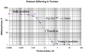
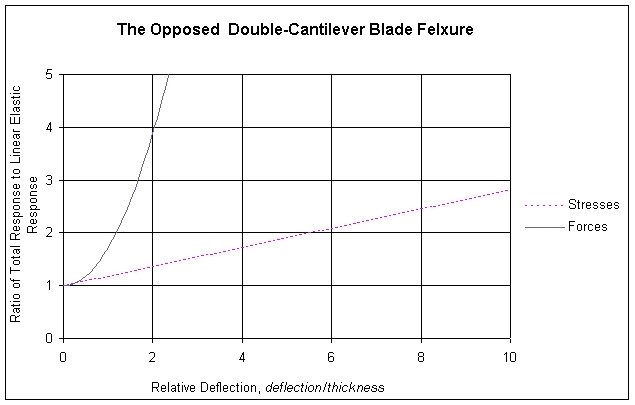
Simultaneously, Poisson stiffening tends to
stabilize the position of the mirror’s surface. It increases, by a
similar factor of 100 to 1,000, the apparent tension/compression modulus, K‘,
of the elastomer between the mirror and the mount (comparing K’ to the
Young’s modulus, E). The bulk modulus, K, for a silicone
elastomer is typically in the range of 150,000 psi to 200,000 psi whereas its
modulus of rigidity may be as low as 180 psi to 200 psi. In thin adhesive
layers the apparent tension/compression modulus, K’, approaches the bulk
modulus, K. Since the Young’s modulus would be about 570 psi,
which becomes a Stiffening Factor of about 300 (see above). The low
modulus of rigidity assures small shear stresses in the bondline due to thermal
expansion and contraction while the high bulk modulus stabilizes the mirror’s
surface in the optical path.
Perhaps you begin to see why this tool is really not a rule-of-thumb. It
is an engineering technique for tailoring the thickness, t, of a
specific elastomeric adhesive, G, to the properties of the mirror, the
properties of the mount and the thermal environment the assembly will see in
service. It also requires the engineer have some understanding of the
Poisson stiffening effect in thin bondlines.
I hope the Holidays left you all refreshed and eager for the New Year.
Here we go again!
Wherever I visit, rules-of-thumb are a hot button topic these days. My
normal response has been that engineers are expected to do better than use
rules-of-thumb. But Fall is here and the Holidays are close-at-hand,
so allow me to be a little more responsive this time.
I develop engineering tools and skills to support and guide my engineering
interests. For instance, I have developed techniques to analyze the surface
figure errors introduced by element mounting techniques. In the spirit
of the coming Season, I will give to one and all (yes, even to Tiny Tim)
one of my engineering tools:
It tells the engineer the minimum adhesive
thickness necessary to limit the thermal distortion of a mounted mirror.
It is easier to use than a finite element code and probably more accurate.
I do not, myself, consider the above expression
a rule-of-thumb but rather one of several engineering tools for use in these
kinds of problems. The curious may read my original paper, SPIE: 6665-03,
2007. The expression is formed by substituting equation (6) into equation
(10), both from the subject paper. I hope you find it as useful as I have.
It’s about as close as I get to a rule-of-thumb in my practice.
Now, let us turn to the approaching Season: The Joyous, Tumultuous,
Boisterous, Extravagant Holiday Season from All-Hallows Eve to Twelfth-Night.
We can talk about engineering tools, and rules-of-thumb, any old time.
“To design or to analyze? Aye, that is the
question.” My apologies to the Bard.
I spent the first half of my career in design. But even as a designer I
was always a numbers guy. I wanted to know why some things worked and
others did not. And I found that the numbers could actually help explain
the workings of things. An example:
I designed the first IR missile active jammer to go into the Navy’s service
(AN-ALQ-123). The IR source was fragile and had never been qualified for
military use. I was frustrated by the reluctance of the structural
engineering department to support me. They wouldn’t touch the quartz,
Lucalox and niobium that the source was made from. Nor would they let me
anywhere near their finite element code. So, I had to run the tests to
determine its fragility and then analyze my mounting design to assure that the
IR source could survive the “cats-n-traps” of carrier take-offs and
landings. I even had to write my own source code for the analysis. It
worked! The design was a grand success and hundreds of -123s entered the
Navy’s inventory. It even made the cover of the Old Crows monthly
magazine. I was a proud papa.
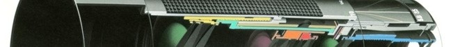
I still design. Here’s a view of a newer design job. It’s an active
stand-off sensor
consisting of a zoom lens with five moving lens
groups, all servo controlled, plus a sixth movable lens group to control the
focus at a distant target. I gave my client all of my design files and
they took it from there. The last I heard, the prototype was working just
fine. There’s a really hard part to design consulting though: Letting
someone else adopt the offspring.
Numbers are a lot less sentimental. I do a lot of analysis these days but
I still think as a designer. Luckily, as an engineer I can
work both sides of that street.
I’ll be talking-up my design tools to the analysis folks at the MSC Software
Users’ Conference in Santa Ana on October 5th. (Just as I talked-up my
analysis tools to the design folks at the SPIE Symposium in August.)
Will I see a few of your cheerful faces there on the 5th?
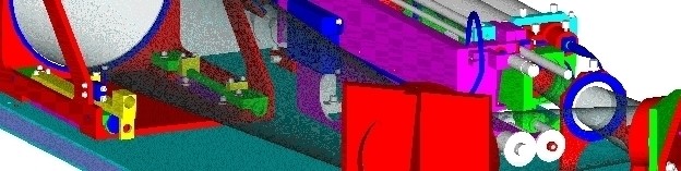
I recently completed an assignment to assist a client in the design of a low-cost high-performance cryogenic (LN2) dewar for infrared detectors. The design include some powered optics as well as the usual creative arrangement of baffles and stops. One of the big challenges was to achieve rapid cool-down from room temperature for all the internal parts of the assembly. We relied on data (see the chart) I developed some years ago and have used numerous times with success. It needs to be scaled for flange materials, thicknesses and other factors of course.
I’ve used these data in electronic equipment, temperature
sensitive machinery, stable space structures and other places where
joint conductances in a vacuum environment have been important. In this
case we were able to achieve a thermal time-constant for the chilled mass
(including baffles and stops) of under 45 seconds. In addition it was all
self-aligning and designed for rapid assembly and test. It was a great
challenge with an equally great group of people.
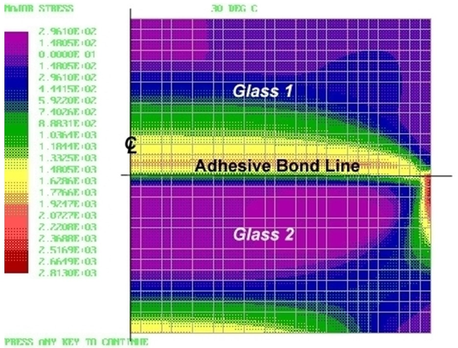
I recently completed a job as an advisor to an airborne multi-spectral sensor system project. My tasks included advice on lens mounting (metal rings vs. adhesive bonding), environmental sensitivities (temperature, vibration and shock), alignment procedures (tooling and adjustments) and manufacturing processes (bonding, glass finishing and failure analysis).
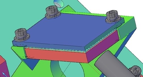
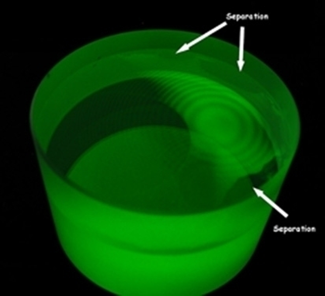
A major concern was the fracture of cemented lenses at high and low temperatures. Understanding the physics of glass fracture was instrumental in both understanding the causes of the fractures of cemented assemblies and designing them to avoiding failures in the service environment. The figures below show the analysis and test of a cemented glass coupon. The contour plot shows the stress distribution in the test coupon and the photo shows the resulting de-lamination and fracture at low temperature.
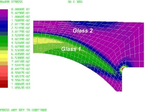
In one of the finished cemented doublets, analyzed below, the fillet in Glass 2 needed special finishing to strengthen it against the stresses at low temperature.
This project was very challenging. Great sport!
I hope your summertime was as interesting as mine.
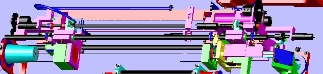
I have recently finished the mechanical design of a very high precision optical vibrometer (it can measure picometer motions at distances of kilometers). I helped to conceive the instrument and my name is one of those on my client’s patent application. It all came out of a brain-storming session about two years ago. It was intended for use by one individual so size and weight were critical.
The design was developed as a 3D solid model in AutoCad 2007. A partial view of the assembly is attached. It is a zooming optical system with six (6) moving lens groups. The lens groups are all servo-controlled. An alternate lens attachment (not shown) permits working distances as short as 50 meters. The layout along with indentured drawing and parts lists were delivered to my customer who wished to prepare the (160 or so) mechanical drawings in-house. They converted the AutoCad file to ProE for their draftsmen without difficulty and are now proceeding into the hardware.
I’m looking around for another interesting project. If you think you might have something I’d like to talk to you about it.
I hope the beginning of 2007 has found you healthy and prosperous.