Optomechanics – Using Ivory for Early Structural Concepts

Colleagues:

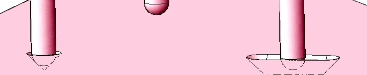
If spherical surfaces didn’t make pretty good images we’d live in a whole different world.  It seems that optics is an art that was just meant to work.  The mechanics?  Well, that’s maybe a whole different story.

I recently helped to demonstrate that a proposed optical system could be made to work.  It’s stability requirements were 2 1/2 times tighter than the earlier system on which the proposal had been based, and the earlier one had been a challenge in its time.  That extrapolation was a risk that the contractor had to eliminate very early. 

So, the CAD engineer and I shared a cubicle.  He collected information on 
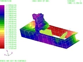
all the stuff that had to go into the system.  I created a structural 
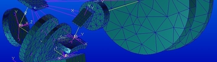
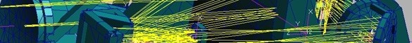
finite element model to analyze the image stability:  I started with the CodeV prescription, which I read into AEH/Ivory and then imported the Ivory file into Patran; I also 
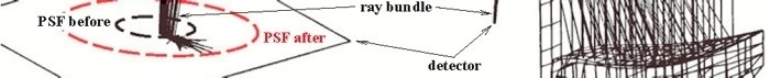
imported into Patran the step-files (and ray bundle) for all the optical elements; I attached the Ivory file to the elements (Any time I moved an element I could then read the resulting motion of the image on the detector); finally, I imported into Patran the proposed flat honeycomb plate to which the optical elements were to be mounted.  The boring part was over.

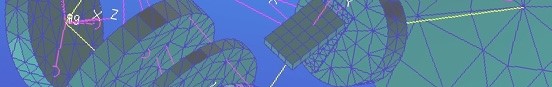
And the real fun began.  I used Patran as a design tool:  I put cells around each of the optical elements; I tied the cells down to the flat plate; I ran a 6 DOF rigid body check and a 3 axis static gravity check in Nastran.  Everything behaved well computationally.  But in random vibration it was out of bed by ~3X.  There was work to be done.

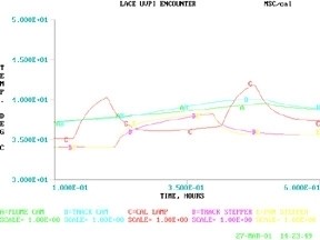
With the AEH/Ivory data imported to Excel I could identify which elements were the big drivers of the image motions.  So, I started beefing up the bracing on 
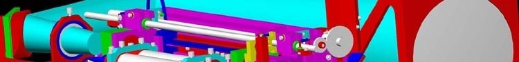
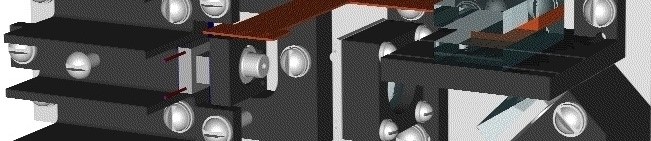
those elements.  The CAD engineer was checking my work while he started his own modeling effort.  He guided me in positioning the optical mountings and I guided him in locating the other services (electronic, thermal, servo, mechanical) that had to work in proximity to the optics on the inner gimbal.  The bracing and the services all had to fit.  Ultimately, we (he and I) were able to reduce the image motions by over 3X and show safe margin on the stability requirements with everything on the gimbal.

All of this was done in the opening days of the project.  In fact, if you cannot make the optical system work when the design spaces are malleable, you will be unlikely to make it work later.  It only gets harder (and I’ve been there too). This early structural concept was itself malleable and would change over time as all of the disciplines agreed to the design.  It might be months before all the CAD interfaces would be settled.  Meanwhile, the project had a structural concept that promised to meet the stability requirements and could guide the detail mechanical design.  And an engineering tool for occasional spot-checks and trade-off studies.

Joy and Happiness!

Ahhh… April.

Al H.
4-16-14

Optomechanics – Save Time with Ivory

Colleagues:

Skeptics like to tease me about using my own software tools to create optomechanical models in finite element codes.  I could simply use the coefficients provided by the optical designer, they suggest.  In a way they’re right.  But I have found that my software allows me to enjoy more of my evenings and weekends.  Let me explain:

The task is to incorporate the optical image formation properties into a structural finite element model.  Rigor is required because small modeling errors can create large misleading results in the subsequent analyses.  A complete set of coefficients and congruent descriptionsof the geometries are essential for a properly formulated optomechanical model.  This allows the optomechanical engineer to validate the integrity of the entire system model with what are called “rigid-body checks.”

But, how to satisfy the “complete” and “congruent” criteria?  Well, I use Ivory.

Now, about the importance of those rigid-body checks:

First, structures:  A rigid-body check exercises the otherwise unconstrained complete model in three translations (Tx, Ty and Tz) and three rotations (Rx, Ry and Rz).  The check discloses malformed elements, erroneous constraints and other errors, which the engineer must correct to have confidence in subsequent analytical results.  It’s a tried-and-true method for checkout of structural models.

Then, optics:  In the optics domain the image motions on the detector during rigid-body checks should be either computational zeros or the effective focal length depending on the status of the object being imaged.  If the model’s image motions contain anomalies (motions other than 0. or the efl) in any of the whole model’s rigid-body motions then the model is poorly formed and the optomechanical engineer must correct it before relying on any subsequent results.  This is a tried-and-true method for checkout of optomechanical models.

Without a complete set of optomechanical coefficients and assured congruent geometries it is very difficult to tell whether any anomalies are artifacts of geometric differences or of inaccurate and/or missing coefficients.  Small imaging anomalies can create large errors in the analyses.  But even small (or perhaps “Especially small”) anomalies can be very time consuming to find and correct.  There are many potential sources of small errors.

That’s where my software lets me enjoy evenings and weekends.  I start with a complete set of Ivory’s coefficients and congruent geometries (from the optical designer’s prescription), check their validity in a simple finite element model (with rigid-body checks) before putting them into the structural engineer’s larger model of the system. 

When the two are married, Voila!  Bliss!  Well, fewer surprises anyway, and more evenings and weekends for me.

So, don’t spend your Holidays in front of your work-station when you should be with your family and friends.

The Season’s Cheer to you all.  I can almost hear the sleigh bells coming.

Al H.
11-12-13

Optomechanics – Ebony vs CodeV and Zemax

Colleagues:

As a coda to last weeks missive I reserved the knottiest part for today, All Hallows Eve.

My optical design friends like to solve for the point spread function in a lens design code like CodeV or Zemax.  To achieve the same accuracy as my Nastran analysis they would require the use of the first 5,280 Zernike polynomials in the series.  With some effort the number could possibly be reduced to just 264 from among those polynomials.  Then they would trace the rays.  Have any of you ever used 264 Zernike polynomials in a lens design code at the same time?  Great Fun!

My Halloween treat for all of you is a direct solution, via AEH/Ebony and Nastran, to structurally deformed point spread functions.  Even More Fun!

Now, Beware the Great Pumpkin!

Happy Halloween.

Al H.
10-31-13

Optomechanics – Optical Analog, OA for Short

Colleagues:

It all began with the “Optical Analog,” OA for short. 

OA is what I’ve called my method for modeling the optical point spread function (PSF) in Nastran structural models of optical systems.  I started simple, modeling an axial chief ray and calculating its motion in object and image spaces when I tweek the structure with forces, displacements or thermal gradients. 

After a few successes it became clear that there was a lot more to be learned by modeling multiple optical rays through the system.  Their motions on the focal plane array would not only indicate image motions but also changes to the PSF (and therefore the OTF, a measure of image quality).

A typical application of the OA was to determine the optical effects caused by residual plastic strains in a light weight metallic primary mirror.  The plastic strains were caused by a sudden shock load.  The figure shows two views of the solution. 

The right side shows a 20 degree sector of the primary mirror model with 44 optical rays reflecting from it.  The mirror had 18 such sectors and the problem was axisymmetric.  The left side of the figure shows the results at the center detector of the FPA (blown-up about 5,000 fold).  The black dashed line shows the size of the geometric PSF before the shock load and the red dashed line shows the geometric PSF after the shock load.  The project had a strict requirement for “ensquared energy” on the detectors and I thinned-out the face sheet and webs until the results were just within the specification.

I wrote Ebony, a computer program, to assist in assembling structural models for OA analyses.  It’s one of my optomechanical modeling tools that I use to help guide mechanical designs.  I tend to put them to work in the early days of a project, while the concepts are malleable.  They’re also useful in “Red Team” assignments to find out, after-the-fact, what went wrong and what it takes to fix it.  AEH/Ebony unifies and couples the PSF to all of the structure in the Nastran model.

If you’re waiting for the beginning of Summer, some good news.  You have only eight months to go!

All Hallow Even comes first, of course.

Joy and good health to all.

Al Hatheway
10-21-13

Optomechanics – Samuel Colt’s Principle of Interchangeable Parts

Colleagues:

Well, San Diego’s history now.  Whew!

Thanks to the OMTG Program Committee for an absolutely terrific two-days of papers (plus a poster session).  Thanks to Phil Pressel for an awesome evening presentation on the Hexagon camera system.  And thanks to Eugene Arthurs and the SPIE staff for keeping it (all the rest of the Symposium) together:  What a herd of cats!

And if you missed the Exhibit Hall, well that’s your problem, understandable but still your problem.

Back to optomechanical engineering.  One of the mechanical engineer’s duties on an optical project is to survey the available mechanical design space looking for problems.  The mechanical design space includes dimensions, temperatures, stresses, deflections, tolerances, pressures, masses, damping, friction, durability, service life, stability, ….  Oh, I shouldn’t leave cost out of the design space either. 

In my practice of the mechanical engineering arts I’ve become a disciple of Samuel Colt.  He’s the guy who introduced the principle of interchangeable parts to the manufacture of his infamous .44 caliber revolver in 1841.  Up to that time firearms were assembled by a gunsmith who would grind, file and polish all the manufactured parts until they fit together and operated to his satisfaction.  Their weapons were very expensive.  On the other hand the Colt revolver’s price was so low that “The Great Equalizer” became available to almost everyone.

My tolerancing method applies Colt’s principle to optical products.  Using influence coefficients from my AEH/Ivory Optomechanical Modeling Tools, I calculate the maximum worst-case assembly errors between the image and the detector in all seven registration variables:  Tx, Ty, Tz, Rx, Ry, Rz and dM/M.  I include the tolerances on the lens design variables (R1, R2, t and n) in addition to all the mechanical dimensional tolerances.  Then I tweak all the tolerances (in a spreadsheet) so that the pain is equally shared between the mechanical suppliers, the optical suppliers and the assembly technicians.  And, all the manufactured parts get used as-is. 

When I describe this principle someone is usually perplexed at how I can do this without using the statistical distribution of each dimension.  I point out that I can put the statistical distributions into the calculations if I choose but they won’t change the maximum worst-case assembly errors.

Scrap is another one of the problems that mechanical engineers work to avoid.  Thank you Samuel!

Well, I bought some candy corn this morning.  All Hollow’s Eve is on the way.

Boo!

Al H.
9-23-13


Optomechanics – The Trap of “Kinematics” vs “Kinetics”

Colleagues:

A while ago I got a call from a sponsor who wanted me to go to a design review in Texas on very short notice.  On arrival I found my name was on the attendance list but no one knew why.  There were a lot of peculiar looks around the registration desk.

I took a seat at the back of the auditorium and quietly made notes.  At coffee break the manager who was funding the subcontract being reviewed came back to introduced himself.  He tried to “talk shop” but I had very little I could say as I’d not been briefed by my sponsor.  I was learning as I listened.

It was mid-morning of the second day that I discovered why I was there.  They had made the hottest doubled-YAG laser I’d seen, but it was unstable.  The laboratory system worked fine but the flight system lost power whenever a door in the room was closed.  Hmmm.

Well, at lunch break I chatted with the laser scientists, who were bewildered by the problem.  So I talked to the mechanical engineers and asked them what they did for the flight system that was different from the laboratory system.  They said, uniformly, “Nothing.”

After lunch, back in the design review, I discovered what “nothing” was.  The mechanical engineers had been directed to put the resonant cavity on a “kinematic mount,” which they did.  It worked great.  In the flight environment however the “kinematic mount” would fly apart so they bolted it together for flight.  The “stiction” in the “bolted kinematic mount” prevented the cavity’s return to its original geometry after a disturbances such as the closing of doors.

In my report to my sponsor I suggested that a simple redesign to replace the failed “kinematic mount” with a “kinetic mount” (i.e., flexures) would probably fix the problem.  But it was too late.   Within a short time the whole project was cancelled.

A warning to optomechanical engineers:  “Kinematic mount” is just a figure of speech.  “Kinematics” is defined as “the study of motion without regard to forces or masses.”  “Kinetics” is the study of motions of masses under the influence of forces.  When asked for a “kinematic” mechanism we should request the allowable motions.  We can usually work out the “kinetics” from there.  If you cannot find out the allowable motions be very, very careful.

I had a good class of students for my tutorial on Thursday at SPIE’s Defense, Security and Sensing Symposium.

Wasn’t Springtime in Baltimore gorgeous? 

Joy to all.

Al H.
5-14-13

Optomechanics – Thermal Problems in Optical Systems

Dear Colleagues:

Let me return to the subject of thermal problems in optical systems.  I mentioned that I often “linearize” the radiation heat transfer problem.  That appeared to confuse some of you so let me explain my position.

I have found that the stability and precision of linear heat transfer solutions uniquely support the precision demanded by high-performance optical instruments.  This is especially true during the design phase when mechanical features need to be traded against each other on the basis of their support for the optical image’s quality and stability requirements.  My experience has been that this technique captures the physics of the optomechanical problem better than the alternatives.

That was true for the example I gave, the LACE spacecraft’s UVPI instrument (above), that made the cover of Aviation Week’s 75th anniversary issue.  The optical sensor head and both electronics assemblies (a power supply and the signal processor) were modeled in a linear heat transfer code. 

I kick around this issue (and a number of others) in my class, “Optomechanical Analysis.”  I’ve agreed to present the class in Baltimore on May 2nd at SPIE’s Defense Security + Sensing Symposium.  If you missed it in San Francisco here’s another opportunity:

http://spie.org/app/program/index.cfm?fuseaction=COURSE&export_id=x12502&ID=x6771&redir=x6771.xml&course_id=E2019181&event_id=1042005&programtrack_id=634

Spring is here!  Can you believe it?

Al H.
3-19-13

Optomechanics – How the Instrument Might Fail

Dear Colleagues:

I had a terrific group of students for my class, “Optomechanical Analysis,” at Photonics West.  It was a generous mix of the disciplines that support the optical industry.

One of the things I teach is how I calculate the ways in which the nearly-a-myriad mechanical design variables can affect the performance of an optical instrument.  A simple example I use is the net effect of tolerances on the position, orientation and size of the image.  The tolerances I address include those on the optical elements themselves.  This allows the engineering team to balance the mechanical tolerances and the optical tolerances.   I take the sum of the absolute values of the effects of the individual design tolerances. 

I am usually challenged by at least one of the students that the root-sum-square of the effects gives a more reasonable value for an assembled instrument.  I respond that as optical instrument designers they are right.  But, I add, as a mechanical engineer I’m also concerned about how the instrument might fail and that the sum of the absolute values gives me better insight into that eventuality, ie., how it might fail in the assembly and alignment process.  I have found that insight very valuable.  The analysis not only alerts me to possible worst-case scenarios it identifies the major contributors to the problems and suggests available corrective actions. 

All in a day’s work.

Ciao, from Baghdad by the Bay.

There will be more, but after Valentine’s Day.

Al H.
2-7-13

Optomechanics – The Intersection of Heat Transfer, Structures and Optics

Dear Colleagues:

A Happy and Joyous New Year to you all!

What a year 2012 was:  two structural window designs, three spectrometers, two cryogenic dewars and an extended-band imager.  Each of these was pressing the limits of the mechanical arts in one way or another.  Then there were the calls for help, or just to say hello, that filled the smaller spaces.  A great time. 

One recurring theme in my work has been the intersection of heat transfer, structures and optics.  The common issue is stability, either static or dynamic, of the optics.  This is a tricky combination because the three disciplines are, in most ways, mutually independent.  The trickiest part seems to be getting the heat transfer results (temperature fields) into the structural model in a reasonable fashion.  “Reasonable” is the key word here.  The engineer faces some difficult choices to achieve optical accuracies.

An approach, for design purposes, has been to linearize the radiation heat transfer and run the whole problem in a finite element code such as MSC/Nastran.  The temperature fields can be made to agree reasonably (there’s that word) well with the Sinda results, ~1% or so.  Import an AEH/Ivory optomechanical model of the image into the MSC/Nastran model and you have the ultimate thermo-opto-elastic engineering design tool.  Fiddle with the mechanics, either thermal or structural, and see the results in the image!  All in one computer model. 

An image from one of my instruments was featured on the cover of Aviation Week’s 75th anniversary issue.  (Well, yes, I have been at this a while.)

Now, most important of all…

Don’t forget our conference in San Diego in August.  Submit your paper abstracts at http://spie.org/OP303 and call me if you have questions. 

Now is your best chance to get in on the fun.

Here comes 2013….  Hang on tight.

Al Hatheway
1-8-13

Optomechanics – A Collaborative Art

Colleagues:

Optomechanical engineering is a collaborative art, a fascinating blend of optics, machine design, structural mechanics, servo controls and heat transfer.  I tend to emphasize my (mechanical) contributions in these missives.  But enough about me.  This time I want you guys to stand up and take the bow.  Let’s list at a few topics from the recent past:

Membrane optics research (of 2-28-12)
My contribution of designing some test facilities and helping with the tests was nothing compared to the conception of the telescope it was intended to support.  My thanks to the telescope designer, the lab technicians who ran the tests and the structural engineers who interpreted the results.  (Applause)

Tensile stresses in ring mounted glass lenses (of 8-31-09)
A dear friend and colleague persisted in his belief that glass was too fragile to be mounted in metal rings.  A survey of the literature showed no solution for this load condition and the nearest ones, point load and line load, were unreasonable.  So, I got out my pencil (remember those?) and developed the solution for ring loading.  My thanks to my dear friend.  (More applause)

Mounting mirrors with elastomers (of 2-6-12)
The optics community has been searching for the perfect “athermal” mounting scheme for years.  Guess what, there isn’t one.  This is one of my contributions to the lore.  Love (and Timoshenko) made me do it.  My thanks (posthumously) to Alexander and Stephen.  (More applause)

Stabilizing lines of sight (of 7-12-11)
I teased the servo engineers, the structural engineers and the “optikers” somewhat mercilessly.  It was entirely rhetorical.  They were the heroes of the story.  No one gets down to microradian stability levels on moving earth-bound vehicles unless they all have done a very good job.  My thanks to the servo engineers, structural engineers and “optikers.”  (Still more applause)

Co-inventing a remote sensor (of 4-17-12)
An optical designer friend thought my nanometer-class structural actuators with his lens design skills would be the solution.  He was wrong.  The best approach was an entirely optical solution, with his lens design skills and somewhat more complicated optics.  It worked.  And I got to do the mechanical design!  My thanks to my optical designer friend.  (And yet more applause)

My list is nearly endless.  And each of you has been a stimulus, a catalyst and a joy to have as a friend and a colleague.

Now, all of you, step forward and take a bow (or two or three).  (Deafening applause)

Thank you all for allowing me to participate in your adventures.

Rejoice on our Independence Day.

And happy Summertime to all.

Al H.
6-28-12