Optomechanics – LCD Design Built Right from the Beginning

Colleagues:

Do you remember the Great LCD Projector Wars?  I certainly do! 

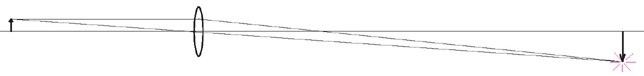
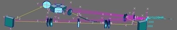
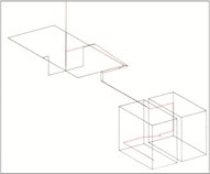
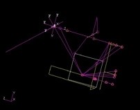
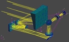
One of AEH’s jobs was to align three LCD images on the screen to 1/10th pixel accuracy and hold them there over long periods of time and over large swings of temperature.  The alignment was performed with adjustable fold mirrors to control the Tx, Ty and Rz degrees of freedom of each image.  A simple Ivory-in- Excel analysis told us it required a stroke of 17 mr. and a resolution of 0.00026 mr. on each of the fold mirrors.

AEH had some other resources to bring to the table as well.  We were able to 
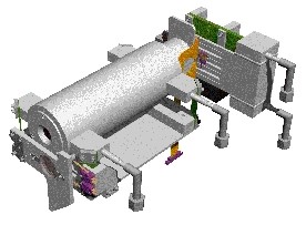
adapt AEH’s patented set-n-forget actuator technology (Intended for JWST) to the design and manufacture of the mirror mounts.  There was a bit of a breathless interval, however, because AEH could not measure the sub-microradian resolution.  The test was to install the mounts and turn on the projector.  The system worked wonderfully, which verified the precision of the mirror mounts and the Ivory analysis.

Here’s to taking care of three images!

Well, that was then and now is NOW. 

The great September 1/4 off sale of AEH/Ivory 3.0 Optomechanical Modeling Tools has only a few more days to run!  Reserve your copy today.

Happy Autumn.

Al H.
9-23-15

Optomechanics – Simulation vs Analysis

Colleagues:

Recent events have caused me to contemplate distinctions between simulation, on one hand, and analysis, on the other.

AEH was asked to determine the root-causes of a thermal shift in the back focal length of a lithographic lens.  The optical design couldn’t predict it. 

The optical, structural and thermal physics were modeled (we call it “Unified”) in a single code, MSC/Nastran.  The deviations from the actual physics (including simplifications) were noted and quantified.  Check-out results were validated against CodeV to prove their optical rigor.  The analytical results agreed well with experimental data.  Their agreement was limited by the mesh in the finite element model, which is typical in optomechanical problems, and it had been noted among the deviations.  The sources of the thermal shift became obvious in reviewing the output data.  These observables-in-the-data are called “diagnostic vectors.”

AEH calls this approach “Unified Analysis” because it keeps all the data together in a unified database, which is often one printable output file.

If your methods aren’t initially validated, if you haven’t been able to quantify the deviations between your methodology and your sciences and if you cannot trace backward from the “effect” to the “cause” then you’ll probably not recognize the diagnostic vectors, nor be able to identify the sources of problems and formulate solutions.

In the age of eye-candy simulations these practical steps often get lost.  Visuals are good but it’s the numbers, including how they’re derived and how they’re used, that counts.  That’s analysis.

When the numbers are important AEH will be there to help you.

Oh my!  School has started!  Good Luck to all the children.

Al H.
8-24-15

Optomechanics – Completing the Zemax Prescription with Ivory

Colleagues:

Well, I’m just back from a week in San Diego for SPIE’s Optics+Photonics meeting.  WOW!  Everybody seems to have some way to “model” optomechanical behavior but nobody seems to know how to verify that the results are right.  That’s why I created “Unified Modeling” (the Ivory and Ebony Optomechanical Modeling Tools):  to provide the engineer verifiable confidence in the results. 

A good friend of mine likes to declare “You need to know the answer before you do the analysis!”  Cute, huh?  It always goes over well from the back of the room during a CDR.  Well, the next-best-thing (I have found) is to have used the same procedures and theories to analyze a case (any case) for which you already know the answer.  One of my favorite test cases is called a “six degree of freedom rigid body check.”  You put the model through three translations (X, Y and Z) and three rotations (Rx, Ry and Rz).  In optical systems it’s easy to predict the image motions on the detector.  They’re either 1.0, computational zeros or some predictable fraction of the back image distance.  And, you don’t need a finite element code.  You can do it all in a spreadsheet.

AEH analyzed the stability of a hyperspectral sensor.  Our client provided the optomechanical influence functions based upon the Zemax optical design.  The random analysis showed that the image stability was out of specification by an order of magnitude.  A subsequent six degree of freedom rigid body check showed large values in stead of computational zeros.  A review of the influence functions showed that they were incomplete.  AEH put the Zemax prescription into Ivory to get a complete set of influence functions.  This six degree of freedom rigid body check showed computational zeros across the board in a spreadsheet!  And subsequent Nastran random stability analysis predicted the performance would be within specification.  Which it ultimately proved to be during qualification testing.

Unified modeling provides traceable modeling performance and helps to keep an engineer’s tools sharp.

School starts next week.  Good luck to all the children!

Al H.
8-21-15

Optomechanics – Is in the Details

Colleagues:

Optomechanical engineering isn’t always big stuff:  hyperspectral sensors; ISR systems; image trackers; boresight control; etc.  There’s a lot of fun in the small stuff too.

For instance, how can you verify that an ultra-light mirror will be 1/8th wave or better when used in space?

How do you fix a lens assembly product when a large fraction of them fail the MTF test?

How do you drive a lens 10 mm with only 300 nm of runout?

A wag might declare, “It’s all in the wrists,” but there’s a whole lot more “fun” than that implies!  The Devil is often in the little details.

Yes, AEH does big stuff, we enjoy the small stuff and we make house-calls too. 

Whatever helps you!

I’ll be looking for all of you in San Diego in a few days!

Al H.
7-30-15

Optomechanics – Some Stuff AEH Built

Colleagues:

Every once in a while we at AEH get a chance to get our hands dirty.  You know, build stuff, install stuff, test stuff, fly stuff…  Here’re a few examples.  The first is a “cryogenic” vacuum test facility for qualification and acceptance testing of ISR focal plane arrays.  AEH designed, built and delivered them to fit into the client’s LN2 bell jar system.

The second is an airborne, gimbal mounted, spectrometer for environmental studies over the Arctic Ocean during mid-winter.  A team at AEH designed and built the gimballed sensor system, installed it (in Alaska) into the flight vehicle (a helicopter) and got FAA certification to fly the system in civil airspace.

Then there are the submicroradian-class adjustable (set-n-forget) fold mirrors for ultra-precise alignment of wavefront bundles.  No cold “weather” here, just high altitudes and awesome vibrations.

AEH is known primarily for analysis, but it’s the non-linear stochastic process of synthesis (better known as design) that makes it all work.  That’s engineering.

I’ll be expanding on this topic in a couple of papers next month at Optics+Photonic in San Diego.

It’s all great fun!

Al H.
7-7-15

Optomechanics – Save your Budget: Identify Problems Early

Colleagues:

How does a mechanical engineer identify problems early?  He or she runs estimates and analyses, maybe solving two or three degree of freedom (DOF) lumped-parameter problems via simultaneous equations in a spreadsheet.  Estimating surface temperatures on the outside of a cast housing comes to mind with simultaneous radiation, convection and conduction needing to be considered. 

But, throw in optical imaging behavior and the number of equations explodes.  The optomechanical engineer deals with not only the structural and thermal equation but also the 49 equations for each optical element’s effect on the system’s image.  For even modest optical systems this swamps the engineer’s conventional methods.  Who’s going to solve a 100+ equation problem in a spreadsheet?

It’s one thing to write about lumped-parameter optomechanical modeling. It’s a whole other thing to actually do it.  The optomechanical engineer needs optomechanical toolsHere’s a “relatively simple” 874 equation (DOF) optical/structural lumped-parameter model:

All of the 784 optics equations were modeled in AEH/Ivory and imported to the MSC/Nastran lumped-structural model (90 equations) for numerical solution.  The Nastran run identified critical thermal alignment challenges, the solution to which enabled a successful telecoms product.  Assembling and running simple lumped-parameter optomechanical models saves budgets, saves schedules and snatches success from the jaws of failure.  That’s engineering.

If you have questions give AEH a call.

I’ll talk more about this in San Diego at SPIE’s Optics+Photonics Symposium, come August.  We’ll have a two-day conference, poster sessions and an evening meeting of the Optomechanical Engineering Technical Group.  It’ll be a great time with technical exhibits, banquets and camaraderie.  I hope to see you all there.

Meanwhile… identify problems early, stay on top and keep your tools sharp!

Al H.
6-10-15

Optomechanics – Prepare for Success Early

Colleagues:

Optics is an art that’s just meant to work… until it doesn’t. 

The optomechanical engineer’s job is to survey the available mechanical design spaces looking for optical problems.  The engineer identifies the problems early, gets on top of them and stays on top all the way through.  MSC Software Corporation recently published a Case Study on this subject.  Here’s the link—

Optomechanics at MSC

Many problems can be anticipated and avoided by using relatively simple, lumped-parameter models in the beginning of a project.  If the project waits until the distributed properties are well defined it may be too late and the budget and schedule considerations may even shut the project down.  Optomechanical analysis is at least an order of magnitude trickier than the individual disciplines alone.  So the engineer has to have tools, and that means being able to couple the structure to the optical behavior in a single code.  AEH uses MSC/Nastran and AEH/Ivory.

Here are two examples, one a success the other a failure.  Both were gimbal-stabilized telescopes of roughly the same size:

The failure was a project that would not let the lumped parameter LOS model be run in the beginning but insisted that the analysis model be prepared from the finished engineering drawings.  The full-up analysis showed an unstable LOS.  Redesigned solutions were possible but costly. This project was cancelled. 

The successful project was able to demonstrate sufficient margin of safety with the lumped parameter LOS model that a full-up optomechanical model wasn’t needed.  The structural engineers could concentrate on strength and safety.  This project was fielded. 

Neither outcome was intuitive or obvious at the projects’ beginnings but their results couldn’t have been more stark.

Powerful tools, simple models, early in the project:  The eye-candy may be poor but the numbers can save the engineer’s buttons.

Spring is lovely in Pasadena.  I hope you’re enjoying it as much as I am.

Al H.
5-14-15

Optomechanics – Bad Behavior in Complex Systems

Colleagues:

One of the challenges for a mechanical engineer is to determine the dominant drivers of bad behavior in complex systems.  The behavior may be observed during service, in environmental tests or system analyses.

In optical systems AEH segregates the effects of each degree of freedom (Tx, Ty, Tz, Rx, Ry, Rz) of each optical element (1, 2, 3, …, detector) and plots the cumulative sum which, in the case below, exposes the major offending elements to be 1 and 5 (see chart).  The engineer may then objectively recommend structural design changes that will stabilize the offending optical elements and improve the optical performance of the structure.

I’ll be presenting the details of this approach in a paper during SPIE’s Optics+Photonics Symposium in San Diego this August.  I hope to see you all there.

In the meantime, if you have questions just give me a call.  I’ll be here.

Happy St. Patty’s Day.

N’Blarney ‘ere, b’Gorah!

Al H.
3-9-15

Optomechanics – The Route 66 of Optomechanics

Colleagues:

OK, enough about software.  After all, we all run software.  It’s AEH’s understanding of how to apply engineering tools, including software, that makes the difference.

To wit: design an airborne optical image correlator.  Stabilize hyper-spectral imagers.  Design aircraft structural-optical windows.  Analyze detector cool-down times.  Test metal-foil optical elements.  Design nanometer-class alignment mechanisms.  Minimize the thermal impedance in a laser cavity.  Co-invent an infrared scanner.  Stabilize a gas-dynamic laser cavity.  Analyze thermal instability in lithographic lenses.  Establish intellectual property rights in cinematographic lenses.  Analyze dynamic stability of a free-space laser-com system.  Design a stand-off optical vibrometer system.

I’ve written about many of these at one time or another.  But another big interest today seems to be, “Where do AEH’s jobs come from?”  Well how about Barrington, Huntsville, Albuquerque, Carson, Dallas, St. Louis, Corona, Seattle, Palo Alto, Princeton, Los Angeles, Rochester, Tucson, Anchorage, San Diego, Linthicum, Mountain View, North Hampton, Azusa and, yes, even in Pasadena it’s been optomechanical engineering that AEH has done.

However you need help, wherever you need help AEH is there

N’Blarney ‘ere, b’Gorah!

Al H.
3-4-15

Optomechanics – Ivory and Cluster Lenses for Panoramas

Colleagues:

I’ve shared with you the tale of the errant window in a vacuum chamber where the issue with the instrument under test was less a change of the effective focal length than a change in the back focal length.  Well, here’s another tale along a similar vein.

It concerns a lens for cameras used in clusters to make large panoramic images stitched together from the smaller individual images.  The lens had to be entirely passive, no adjusting mechanisms were allowed.  They came up with an ingenious combination of glasses that would produce the required image quality as well as exactly balance out the thermal expansion of an aluminum alloy structure so as to stabilize the effective focal length over a broad range of temperatures.  In service tests the image size was perfect for stitching but the image was out of focus at the extreme temperatures.  They had assumed that the second principal plane (and therefore the back focal length) was stationary.

The situation becomes evident when the prescription is put into Ivory.  Importing Ivory’s output file into a spreadsheet permits calculation of both the focus registration sensitivity, Tzi/C°, and the image size sensitivity, DM/Mi-C°. 

Control of two dependent degrees of freedom, image size and image focus, requires two independent variables.  Only the properties of the aluminum alloy in the housing were available so only one of the variables could be “zeroed.”  The back focal length was left to float with the focus registration, TZi/C.  Rummor has it that they finally added a focus mechanism.

The Ivory Optomechanical Modeling Tools provides the engineer access to these behaviors of optical images, avoiding much embarrassment.

The all new Ivory 3.0 is now available with annotated project files, diffraction gratings, Unified Nastran modeling and much, much more.

And just in time for Valentine’s day!

Al H.
2-5-15