Optomechanics – Thermal Problems in Optical Systems

Dear Colleagues:

Let me return to the subject of thermal problems in optical systems.  I mentioned that I often “linearize” the radiation heat transfer problem.  That appeared to confuse some of you so let me explain my position.

I have found that the stability and precision of linear heat transfer solutions uniquely support the precision demanded by high-performance optical instruments.  This is especially true during the design phase when mechanical features need to be traded against each other on the basis of their support for the optical image’s quality and stability requirements.  My experience has been that this technique captures the physics of the optomechanical problem better than the alternatives.
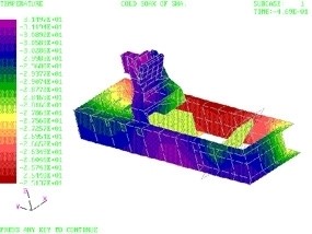
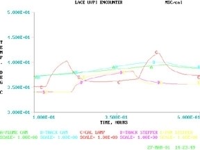
That was true for the example I gave, the LACE spacecraft’s UVPI instrument (above), that made the cover of Aviation Week’s 75th anniversary issue.  The optical sensor head and both electronics assemblies (a power supply and the signal processor) were modeled in a linear heat transfer code. 

I kick around this issue (and a number of others) in my class, “Optomechanical Analysis.”  I’ve agreed to present the class in Baltimore on May 2nd at SPIE’s Defense Security + Sensing Symposium.  If you missed it in San Francisco here’s another opportunity:

http://spie.org/app/program/index.cfm?fuseaction=COURSE&export_id=x12502&ID=x6771&redir=x6771.xml&course_id=E2019181&event_id=1042005&programtrack_id=634

Spring is here!  Can you believe it?

Al H.
3-19-13

Optomechanics – How the Instrument Might Fail

Dear Colleagues:

I had a terrific group of students for my class, “Optomechanical Analysis,” at Photonics West.  It was a generous mix of the disciplines that support the optical industry.

One of the things I teach is how I calculate the ways in which the nearly-a-myriad mechanical design variables can affect the performance of an optical instrument.  A simple example I use is the net effect of tolerances on the position, orientation and size of the image.  The tolerances I address include those on the optical elements themselves.  This allows the engineering team to balance the mechanical tolerances and the optical tolerances.   I take the sum of the absolute values of the effects of the individual design tolerances. 

I am usually challenged by at least one of the students that the root-sum-square of the effects gives a more reasonable value for an assembled instrument.  I respond that as optical instrument designers they are right.  But, I add, as a mechanical engineer I’m also concerned about how the instrument might fail and that the sum of the absolute values gives me better insight into that eventuality, ie., how it might fail in the assembly and alignment process.  I have found that insight very valuable.  The analysis not only alerts me to possible worst-case scenarios it identifies the major contributors to the problems and suggests available corrective actions. 

All in a day’s work.

Ciao, from Baghdad by the Bay.

There will be more, but after Valentine’s Day.

Al H.
2-7-13

Optomechanics – The Intersection of Heat Transfer, Structures and Optics

Dear Colleagues:

A Happy and Joyous New Year to you all!

What a year 2012 was:  two structural window designs, three spectrometers, two cryogenic dewars and an extended-band imager.  Each of these was pressing the limits of the mechanical arts in one way or another.  Then there were the calls for help, or just to say hello, that filled the smaller spaces.  A great time. 

One recurring theme in my work has been the intersection of heat transfer, structures and optics.  The common issue is stability, either static or dynamic, of the optics.  This is a tricky combination because the three disciplines are, in most ways, mutually independent.  The trickiest part seems to be getting the heat transfer results (temperature fields) into the structural model in a reasonable fashion.  “Reasonable” is the key word here.  The engineer faces some difficult choices to achieve optical accuracies.

An approach, for design purposes, has been to linearize the radiation heat transfer and run the whole problem in a finite element code such as MSC/Nastran.  The temperature fields can be made to agree reasonably (there’s that word) well with the Sinda results, ~1% or so.  Import an AEH/Ivory optomechanical model of the image into the MSC/Nastran model and you have the ultimate thermo-opto-elastic engineering design tool.  Fiddle with the mechanics, either thermal or structural, and see the results in the image!  All in one computer model. 

An image from one of my instruments was featured on the cover of Aviation Week’s 75th anniversary issue.  (Well, yes, I have been at this a while.)

Now, most important of all…

Don’t forget our conference in San Diego in August.  Submit your paper abstracts at http://spie.org/OP303 and call me if you have questions. 

Now is your best chance to get in on the fun.

Here comes 2013….  Hang on tight.

Al Hatheway
1-8-13

Optomechanics – Zero Chance for Failure Over 15 Years

Dear Colleagues:

I had one terrific Summer.  I hope you enjoyed it as much as I did.

One highlight of the Season was the analysis of a meter-class optical window to assure safe operation over a 15 year service life in transport-type aircraft.  Safe means zero chance for failure over 15 years (no Weibul statistics for these folks!).  Fortunately, they had selected a glass for which there is good engineering data, i.e. the fracture toughness, the crack propagation rates and the stress-corrosion effects of moisture had been well defined and quantified.  My job was to define the proof test for the new windows that would assure the product safety for 15 years and another proof test to be used at the periodic reinspections.

The procedure is a deterministic one.  The engineer integrates the crack propagation velocity repeatedly over the time of the stress transient until the crack grows to critical size at which time complete fracture occurs instantaneously.  I use MSC/Nastran finite element code to define the stress transient and I use AEH/Jade brittle fracture software to perform the numerical integration.  AEH/Jade allows me to easily vary the initial crack size and the integration time step.  The latter allows me to demonstrate convergence in the time domain which may be very important in complicated stress transients.

Once an acceptable initial crack size has been determined the defining proof test becomes a piece of cake.

Well, that was one of this Summer’s adrenalin highs.

I’m sorry for having been away so long, but I was having way too much fun!  More later, I promise.

Look out!  All Hallow’s Eve awaits you.

Al H.
9-24-12

Optomechanics – A Collaborative Art

Colleagues:

Optomechanical engineering is a collaborative art, a fascinating blend of optics, machine design, structural mechanics, servo controls and heat transfer.  I tend to emphasize my (mechanical) contributions in these missives.  But enough about me.  This time I want you guys to stand up and take the bow.  Let’s list at a few topics from the recent past:

Membrane optics research (of 2-28-12)
My contribution of designing some test facilities and helping with the tests was nothing compared to the conception of the telescope it was intended to support.  My thanks to the telescope designer, the lab technicians who ran the tests and the structural engineers who interpreted the results.  (Applause)

Tensile stresses in ring mounted glass lenses (of 8-31-09)
A dear friend and colleague persisted in his belief that glass was too fragile to be mounted in metal rings.  A survey of the literature showed no solution for this load condition and the nearest ones, point load and line load, were unreasonable.  So, I got out my pencil (remember those?) and developed the solution for ring loading.  My thanks to my dear friend.  (More applause)

Mounting mirrors with elastomers (of 2-6-12)
The optics community has been searching for the perfect “athermal” mounting scheme for years.  Guess what, there isn’t one.  This is one of my contributions to the lore.  Love (and Timoshenko) made me do it.  My thanks (posthumously) to Alexander and Stephen.  (More applause)

Stabilizing lines of sight (of 7-12-11)
I teased the servo engineers, the structural engineers and the “optikers” somewhat mercilessly.  It was entirely rhetorical.  They were the heroes of the story.  No one gets down to microradian stability levels on moving earth-bound vehicles unless they all have done a very good job.  My thanks to the servo engineers, structural engineers and “optikers.”  (Still more applause)

Co-inventing a remote sensor (of 4-17-12)
An optical designer friend thought my nanometer-class structural actuators with his lens design skills would be the solution.  He was wrong.  The best approach was an entirely optical solution, with his lens design skills and somewhat more complicated optics.  It worked.  And I got to do the mechanical design!  My thanks to my optical designer friend.  (And yet more applause)

My list is nearly endless.  And each of you has been a stimulus, a catalyst and a joy to have as a friend and a colleague.

Now, all of you, step forward and take a bow (or two or three).  (Deafening applause)

Thank you all for allowing me to participate in your adventures.

Rejoice on our Independence Day.

And happy Summertime to all.

Al H.
6-28-12

Optomechanics – Optomechanics and the Tolerancing of Instruments

Colleagues:

I will be presenting my tutorial “Optomechanics and the Tolerancing of Instruments” in San Diego on August 13th during SPIE’s Optics and Photonics Symposium.  The course is primarily intended for mechanical engineers and designers in the optics industry and may be of interest to other optics professionals as well.

In the tutorial I develop the full theory of the Optomechanical Constraint Equations (OCE).  They relate the position, orientation and size of an image to the position and orientation of each of the optical elements that form it.  I work through numerical examples to assist the student’s understanding and illustrate the application of the OCE with examples, static and dynamic, from my engineering practice.

The OCE are the basis for the AEH/Ivory Optomechanical Modeling Tools (version 2.6 currently available) that are the mechanical engineer’s first choice for design and analysis of optical systems.

For more details on  the course visit SPIE’s web site,


http://spie.org/app/program/index.cfm?fuseaction=COURSE&export_id=x30628&ID=x30533&redir=x30533.xml&course_id=E1036499&event_id=896190&programtrack_id=1038730


or send your questions to me.

I’ll also be hosting an evening meeting of the Optomechanical Technical Group, probably on Tuesday (but more on that later) as well as cruising the conference rooms, receptions and exhibit halls.  It’ll be a big week!

Hope to see you all in San Diego from August 12th through the 16th.

Al H.
5-7-12

Optomechanics – Just what is it you do?

Dear Colleagues:

It’s been busy the last few months.  Some of you have asked, “Just what is it you do?”  Well, here’s just a sampling:

I’ve researched the intellectual property of mechanisms for focus and diaphragm control in camera lenses;

I’ve analyzed microradian-level image jitter in an off-axis imaging spectrometer (with AEH/Ivory and MSC/Nastran of course);

I’ve co-invented a remote sensing 10:1 zoom system with five moving lens groups, three of which are lenslet arrays.

Who could possibly have more fun than a mechanical engineer in this optics industry?

I hope you will join me in this paean to Springtime.  Joy!

Al H.
4-17-12

Optomechanics – Membrane Properties

Dear Colleague:

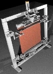
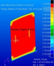
AEH tested, with a client, the ability of metal foils and polymer films to form membranes with optically useful surfaces such as cylindrical conic sections (SPIE:  5494-50, 2004).  AEH subsequently explored the concept using non-linear structural solution sequences in MSC/Nastran. 

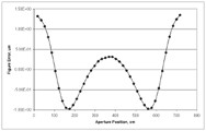
AEH’s study identifies trade-offs among the material properties, dimensional properties, initial conditions and loading.  It also provides the optomechanical engineer design tools to minimize the surface figure errors in real, non-idealized, clear apertures.  For instance, compensate for defects in the membrane such as non-uniform thickness, variable properties and non-planar initial membrane shapes.

AEH:  Cutting-edge engineering for cutting-edge systems.

Al H.
2-28-12

Optomechanics – Elastomeric Mounting of Mirrors

Colleagues:

Please allow me to complete the discussion of my engineering tool for elastomeric mounting of mirrors.

So, according to my previous missive, the elastomer reduces the shear stresses on the back face of the mirror by two to three orders of magnitude compared to a rigid adhesive.  That’s all well-and-good but how do we know that it’s good enough?  Of course those of you who have picked up the source reference (SPIE: 6665-03, 2007) know the answer.  You also know why there are no dimensional quantities (inches, millimeters, etc.) for the mirror in my equation,

In the derivation I assumed that the gravitational sag of the mirror was a reasonable budget for the figure errors induced by the mounting method.  When I equated the deflection of the mirror due to gravity to the deflection of the mirror due to the thermally induced shear stresses on the back of the mirror the mirror’s dimensions (thickness and edge length) dropped out leaving only the adhesive’s thickness, t, the environmental temperature change, DT, the difference in coefficient of thermal expansion between the mirror and the mount,   Da , the modulus of rigidity (shear modulus) of the elastomer, G, and the specific weight of the mirror substrate, sVoila!


So, that’s my engineering tool.  But plugging numbers in is the easy part.  Now the engineer has to go to work.  You’ll find a discussion of the engineering considerations in the source reference also.

Thank you for your patience. 

‘Tis mid-winter and Valentine’s day is nigh.  Ah, the joy of good company!  Thank you all, again. 

Yes Tiny Tim, thank you too.

Al H.
2-6-12

Optomechanics – Bridge the Chasm (between the optical and mechanical domains)

Mid-winter greetings!  Condolences to my Northern California friends about the snow-pack in the Sierras.  Perhaps we can import some from Europe.  It’s one of the things they seem to have in surplus this year.

Structural mechanics is the very nexus of optomechanical engineering.  It has been since at least 1638, the year that Galileo Galilei wrote in his journal, “If I push on this beam how far will it bend and when will it break?”  With that query he became the recognized father of the structural mechanics art.  That was some 28 years after he had turned his telescope on the heavens to become the father of astronomy.  It took even that great man a long time to recognize that the structure of his telescope was essential to stabilizing the planetary images on his retina.  That nexus remains nearly as obscure and difficult today as it was then.  I discuss this situation in my dinnertime talk, “Bridging the Chasm.”

The awkwardness between optics and structures was brought home to me again in a recent project.  I had an opportunity to help a colleague evaluate the stability of the images in a spectral imager.  I built-up the instrument’s structural model from step files generated by the CAD engineer.  I had some challenges in the meshing processes in Patran:  unresolvable singularities, wicked element geometry and that sort of thing.  Checking out the full mechanical model with six degree of freedom rigid body motions and three axis static gravity loads helped to correct the problems in the elastic model

The optical designer gave me a set of influence coefficients he’d prepared in Zemax and I modeled those into the Nastran deck manually.  I was unable to get reasonable results from the optical model in the check-out runs.  In the analysis runs the image motions were wildly, incredibly, out-of-bed.

I was able to show, using an Ivory-generated set of influence coefficients that the structure was behaving reasonably.  The Ivory model should have behaved somewhat like the optical designer’s model, but it didn’t.  The optical designer and I sat down and went through all he and I had done.  I, for some reason, could not relate his optical coordinate systems to my structural model coordinate systems.  We finally agreed to prepare a new set of influence coefficients based upon revised simple coordinate systems. 

Bingo!

Once we took the time to “bridge the chasm” the modeling problems disappeared and engineering could begin.  There are a lot of opportunities for misunderstanding and misinterpreting numbers moving between the optical and mechanical domains.

From optical image correlators to off-axis spectral imagers Ivory has proven to be my indispensable optomechanical engineering tool.

Al H.
2-2-12