Optomechanics – The Calibrated Thumb Technique

Colleagues:

One of my early bosses, Wilford, introduced me to the “calibrated thumb” technique.  The immediate challenge was to anticipate static deflections and resonant frequencies in new design work.  His broader purpose was (I have since come to think) to open my mind about ways to develop my estimating skills.  I was working in airborne IR countermeasures at the time. 

I’ll introduce the technique to you with a much more recent example. 

I had been called in to make dynamic boresight stability analyses for a multi-sensor suite.  It was presented to me as an all-up finite element solid model of the system with three million-plus degrees of freedom.  I incorporated Ivory’s optomechanical constraint equations to calculate the line-of-sight errors for each sensor and the boresight errors between them.  This unified optomechanical model passed the rigid-body checks and static gravity checks just fine.  The calculated boresight errors were small compared to the specification. 

But I had an uneasiness.  There are lots of places in complex models to enter typos, select the wrong property from a long list or drop some decimal places.  How can I settle my uneasiness about someone else’s model?  My client had been around a while and done a lot of good stuff in the past, so I got an idea.

I went out to their shop where a variety of similar sensor systems were sitting on granite surface plates.  I got a height gage with a digital indicator and set it next to one of the systems.  Then I pushed on the system with my thumb applying what I thought to be about 1.0 pound and observed the deflection under the digital indicator’s tip.  I repeated it with two other sets of hardware in the shop.  The deflections were all somewhat different.  That was expected since the systems were of substantially different sizes.  But they’d all been designed and built by this organization.

Then I did a thought experiment, “If I push on the unified model with my thumb how much deflection should I expect?”

I went back to my computer and applied a similar load to the model.  The computed response compared well to my thought experiment.  My anxiety eased and the model proved, in test, to be reasonably accurate.  Whew!

A calibrated thumb is a good thing to have.  Thanks, Wilford.

Of course, my calibrated thumb is one of the tools I try to keep sharp.  When I got back to my home office I checked my thumb with a postal package scale.

Use it or loose it!

Al H.
1-29-15

Optomechanics – Overcoming the Optical Lexicon for Mechanical Engineers

Colleagues:

Reflecting on the year just (barely) passed a couple of older stories keep coming to mind. 

Early-on, a lens designer friend, Tom, asked me to mount an afocal triplet in a weapon sight.  He said he wanted it to be on a kinematic mount.  I hadn’t heard the term “kinematic mount” before so I did a little research.  Mark’s Handbook had no entry.  Maleev and Hartman’s Machine Design had no entry.  Ham and Crane’s Mechanics of Machinery had no entry.  Sears and Zemansky’s University Physics was not helpful.  Finally, in J. L. Meriam’s Mechanics, Part 2, I found a partial definition, “kinematics … the study of the motions of bodies without reference to the forces which cause the motions….”  I went back to Tom and asked him,  “What kind of mount for optics in a weapon sight doesn’t consider the forces involved?”  Well, he was patient in explaining his higher level of abstract reasoning and suggested that I expand my library. 

Some time later I was sent by the Air Force to a design review in Texas and to report what I found.  I wrote you about this a year or so ago.  The physicists had designed one of the hottest doubled-YAG lasers I’d ever seen and they requested that the cavity be installed on a kinematic mount.  The engineers complied with a classic three-ball mount.  It worked like a champ in the brassboard but the flight unit was unstable.  Everyone was perplexed.  Well, it turned out that the kinematic mount wouldn’t survive the service vibration so the mechanical engineers had conveniently provided screws at each of the balls to lock them out for flight.

In the first case Tom and I worked it out, I ate my humble pie and Tom put me on his patent as a co-inventor.  In the second case the Air Force lost faith in the contractor and cancelled the entire project.

One of the challenges faced by mechanical engineers in the optics industry is lexical:  The engineer may hear what is said but not clearly understand what is meant.

To address this challenge the engineer must ferret-out the acceptable mechanical behavior, regardless of how it was originally expressed, and design it into the required structures and mechanisms.  It takes a little extra digging but has proved to be a winning strategy.

And with that. . . A Happy New Year to you all!

Al H.
1-5-15

Optomechanics – Early Adoption Matters

Colleagues:

At AEH we study closely the ways things fail.

It is often said that an engineer’s job is to make things work.  Well, that’s nice.  Tinkerers can do that too.  What’s really required from engineers is to make things work every time.  That’s a little different discipline. 

So, as engineers AEH studies how things fail in order to better know how to prevent bad things from happening:

In optical systems, virtually all “optical” failures result from some defect in the mechanical implementation.  These failures are never corrected by changing the optical prescription.  Well, almost never:  There was the Hubbell primary mirror fix.

Optomechanical problems are best spotted early, while the design resources (size, shape, mass, arrangement, interfaces, etc.) are malleable.  Those resources can quickly become depleted, even unavailable, as they are claimed by other interests:  bearings, servos, electronics, cryogenics, subcontractors, etc.

Early detection requires special tools for the optomechanical engineer.  To assess optomechanical problems the optics and mechanics must be coupled by the engineer, hopefully from the first publication of the prescription, perhaps during the proposal effort even. 

The results of this early optomechanical coupling may only be estimates, but they’re essential.  They give the engineer who uses them a sense of how to guide the design to his desired…, no, to his required destination: 

Spot-on performance with a trouble-free service life.

Early assessment of optomechanical problems is one way we help our clients.  AEH has the tools:  longhand, ten-key, spreadsheet and Nastran. We’ve got all that plus Ivory, Ebony and Jade to interpret the optomechanics for you.

Of course, we can often help after problems materialize and the corrective options have become more restricted.

Joy to all for the Autumn season.  It has arrived!

Al H.
10-6-14

Optomechanics – What do Optomechanics do all day?

Colleagues:

What does the optomechanical engineer bring to the table?  Hmmm…

A  few months ago a structural engineer friend asked me to analyze the strength of a lens assembly that he didn’t feel comfortable with.  It was injection-molded plastic, elastomeric rubber and glass.  OK…

Before that an optics friend challenged me to explain why it might be OK to mount glass lenses between threaded aluminum rings.  So, I did, but it took a while…

Another optics friend got me involved in resolving intellectual property disputes for mechanisms in cinematography lens assemblies…

Then a mechanical engineer friend needed a mass properties trade-off study between BK7 and sapphire for an airborne surveillance window…

Then another optics friend inquired about the possibility of nanometer-class structural actuators for 30 degrees K space optics.  So I designed, built and tested a successful set of them…

And before that I was asked to rationalize the structural damping coefficients to be used in an optical image jitter analysis.

The optomechanical engineer thinks outside the box.  He needs to work outside the box as well. 

Actually, I got that backwards:  He needs to work outside the box in order to be able to think outside the box.  It’s the peculiar demands, outside of his art, placed on the mechanical engineer by optics that inspire in him the intellectual curiosity to find workable engineering solutions.

Besides, he gets to enjoy your occasional company, too.  Thank you.

And, don’t forget to submit your abstract for “Optomechanical Engineering 2015.”
Assure your position in the program now:
         http://spie.org/OPO/conferencedetails/optomechanics
Hmmm… which one should I submit? 

Al H.
12-1-14

Optomechanics – How to Design with Ivory

Colleagues:

When performance is crucial the engineer uses tools to assure it.  Let me show you:

Say, we need a hyperspectral design with a 60 cm entrance pupil and stabilized to less than 15 ur, rms, LOS error in object-space.  We have the physical prescription.  How to get started?

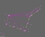
The first thing I do is run the physical prescription data through AEH/Ivory Optomechanical Modeling Tools and import them into MSC/Patran-Nastran to start a system model (1).  The pink lines represent the optics and the yellow lines are structural bar elements with lumped masses. 

It’s a crummy “visual” but a very important first step.  I validate the model with rigid-body checks.  Then I run the model through random vibration adjusting the properties of the bar elements (areas, inertias, materials, etc.) until AEH/Ivory-in-Nastran satisfies the LOS performance requirement (12.3 ur, rms, in this case) with a reasonable combination of properties.

(1) 12.3 ur, rms
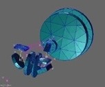
(2) 12.8 ur, rms
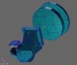
(3) 11.9 ur,rms
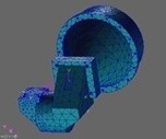
(4) 12.7 ur, rms

Next I incorporate solid models of the optical elements and replace the simple bars with more complicated beam elements (rectangular and circular tubes, some tapered) and optimize their wall thicknesses to maintain the AEH/Ivory-in-Nastran LOS performance (2).  I now have an estimate of a housing geometry (masses, dimensions, thicknesses) that will meet the LOS performance. 

The CAD engineer has decided on a three-piece housing design; an objective, a compound elbow and a detector.  The first section we develop is the compound elbow that holds the grating.  The CAD engineer makes a model which I import into the system model.  When we have an elbow design that maintains the AEH/Ivory-in-Nastran LOS performance in the system model, (3), we move ahead.

We design the objective and the detector sections next, import them, one at a time, into the system model.  We run the model through random vibration adjusting properties to maintain the AEH/Ivory-in-Nastran LOS performance before proceeding.  Finally, (4), we have developed a three-piece optical housing design through an iterative engineering process that supports the required LOS stability.

That’s optomechanical engineering with tools.  No surprises.  No excitement.  Just getting where we need to go, working from the optical prescription.

Now, to play a little…

Oh!  Joyous Summertime.

Al H.
7-7-14

Optomechanics – Preventing Failure

Colleagues:

As an engineer I’m absorbed with understanding the ways that things fail.

It is often said that an engineer’s job is to make things work.  Well, that’s nice.  Tinkerers can do that too.  The fact is that success rarely rewards an engineer while a single failure can nearly ruin him.  What’s really needed from an engineer is to make things work every time.  That’s a little different discipline.

Just ask Ray DeGiorgio, the GM engineer who’s taking the fall for the Chevy Cobalt ignition switch problem; or de Haviland, which nearly aborted the jet age, when a number of it’s Comet model passenger transports very quietly disappeared from the sky, without a trace; or the engineer who messed up the metrology on the Hubbell primary mirror.

So, as an engineer, I study how things fail in order to know how to prevent bad things from happening.

One key to failure prevention is early detection of possible failure modes.  In optical systems, virtually all optical failures result from some defect in the mechanical implementation.  These problems are never corrected by changing the optical prescription.  (Well, almost never:  There was the Hubbell primary mirror fix.)

Early detection requires special tools for the engineer.  To detect optical problems the optics and the mechanics must be coupled by the engineer from the moment of conception.  The results of this early coupling may only be estimates, but they’re essential.  Few early engineering estimates provide elegant eye-candy, and to some people they may not be persuasive.  But they give the engineer a sense of how to guide the design to the desired…, no, to the required destination.  The estimates will be refined and formalized as the design matures and eventually may become deliverable analyses.

The tools the engineer uses must be able to grow with the project from early conceptual estimates to the final NASA, DOD or NTSB reports, a continuous flow of engineering evaluations using the same proven techniques with demonstrable quality within a growing database of design detail as the project progresses.

That’s AEH’s mission and that’s why I study the way things fail. 

And that’s why I’m going to have a terrific Summertime!

How about you?

Al H.
6-27-14

Optomechanics – SPIE

Colleagues:

Summer’s coming, and so is SPIE’s magnificent Optics+Photonics Symposium in San Diego, August 17th through the 21st.  The week will be loaded with optomechanical events and technologies.

On Monday the 18th I’ll be presenting a paper, “Use It Or Lose It,” in Mark Kahan’s conference, “An Optical Believe-It-Or-Not:  Key Lessons Learned III.”  That should be a hoot! 

Then, Bright and early Tuesday, the 19th, there’s a meeting with SPIE staff for planning next year’s Optomechanical Engineering Conference.  That conference will be your place in the sun, technologically speaking, so get your abstracts ready for submittal and spread the word to your friends and associates.

Tuesday evening, 8 to 10 PM, the Optomechanical Engineering Technical Group will hold their annual West Coast Bash.  Our speaker will be Tony Hull, Adjunct Professor of Astronomy and Astrophysics at the University of New Mexico.  He’ll be addressing the primary mirror material selection process for spaceborne telescopes and how it drives the architecture and planning of these systems. 

Wednesday, the 20th,I’ll be teaching my tutorial, “Optomechanical Analysis,” all day to a bunch of bright-eyed students.  This is aimed primarily at mechanical engineers and I try to give them some new tools to relate their mechanical engineering decisions to the optical behavior of their systems.  This material may also be of interest to other optics professionals, even structural engineers.

Wednesday evening is SPIE’s Awards Banquet where all of the elephants of the academy and industry gather to celebrate new honorees.  This is always a great event and I’m sure that Phil Stahl, our President, will put his usual high gloss finish on the whole program.  I may be weary from teaching all day but this is always a must-do event for me.

And Thursday, ahh… Thursday:  Finally, I’ll get to cruise the exhibits, mingle with colleagues, meet new people, and catch up on the technology in the conference rooms.  Then at the end of the day, after the exhibits close, a few of us will go out to a local bistro for a toast-n-roast dinner (maybe with some red meat, even!).

It’s all one great week-long event:  More material than you can ever hope to capture in real-time.

And I hope to see you all there.

Al H.
6-16-14

Optomechanics – Preventing Boresight Errors

Colleagues:

If engineering can be said to have a “purpose” it might be “to survey the available design spaces and guide the design process to avoid future failures.” 

An especially tricky aspect of optomechanical engineering is avoiding unacceptable boresight errors among instruments during thermal transients.

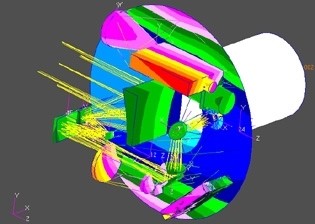
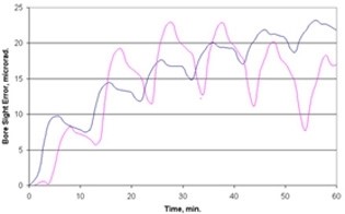
One example is a target designator that was required to operate on a 50% duty cycle with a maximum on-time of five minutes.  The boresight was important because the laser and the imager operated in different bands so the operator would not be able to “see” the laser spot in the FOV.  The boresight error was required to be less than 15 microradians over one hour of operation.  As shown in the figures the maximum boresight error was predicted to be 12 microradians after about 54 minutes (blue is the laser and pink is the imager).

In order to achieve acceptable stability it had been necessary to add some bracing between the laser beam expander and the imager’s primary mirror.  Adjustments in the position of the laser had also been necessary.  These changes were made early enough in the design process to avoid a major disruption of the program. 

AEH/Ivory Optomechanical Modeling Tools provided the critical link required to assure the system’s optical performance.

Baltimore was glorious and I had a great group of students.  But it’s good to be home!

Enjoy the fresh Springtime.

Al H.
5-27-14

Optomechanics – Early Viable Design Concept

Colleagues:

Ok, ok.  I loaded you with a lot of details last week.  But the good news is, “That’s all there is.”  A few day’s work at the beginning of the project and you have a viable design concept with which to proceed and have developed an engineering tool to spot-check the design during it’s progress. 

However, I must admit to an ulterior motive:  Many of my optical colleagues only see the “eye candy” produced by SolidWorks, ProE or CATIA and are only vaguely (at best) aware of the “continuous stream of numbers” the mechanical engineer produces to assure the safety, reliability and optical function of his designs.  The numbers have little eye appeal and optics should be visual at a minimum, right?  Well, any draftsman can produce the eye candy but only an engineer can assure the resulting product.

I was able to enjoy my Easter weekend because I got that job put-to-bed.  We know how to make it work.  We’ll do some design checks as the design matures. Then we may put the optical behavior into the final FE model the structural engineers will create for their safety analyses.  Or we may not.  And that’ll be OK since we know that we’ll have good optical margins of safety.

Speaking of Easter, I hope you all had a great weekend holiday.

And thank you for all of your support over the years.

Al H.
4-24-14

Optomechanics – Using Ivory for Early Structural Concepts

Colleagues:

If spherical surfaces didn’t make pretty good images we’d live in a whole different world.  It seems that optics is an art that was just meant to work.  The mechanics?  Well, that’s maybe a whole different story.

I recently helped to demonstrate that a proposed optical system could be made to work.  It’s stability requirements were 2 1/2 times tighter than the earlier system on which the proposal had been based, and the earlier one had been a challenge in its time.  That extrapolation was a risk that the contractor had to eliminate very early. 

So, the CAD engineer and I shared a cubicle.  He collected information on all the stuff that had to go into the system.  I created a structural finite element model to analyze the image stability:  I started with the CodeV prescription, which I read into AEH/Ivory and then imported the Ivory file into Patran; I also imported into Patran the step-files (and ray bundle) for all the optical elements; I attached the Ivory file to the elements (Any time I moved an element I could then read the resulting motion of the image on the detector); finally, I imported into Patran the proposed flat honeycomb plate to which the optical elements were to be mounted.  The boring part was over.

And the real fun began.  I used Patran as a design tool:  I put cells around each of the optical elements; I tied the cells down to the flat plate; I ran a 6 DOF rigid body check and a 3 axis static gravity check in Nastran.  Everything behaved well computationally.  But in random vibration it was out of bed by ~3X.  There was work to be done.

With the AEH/Ivory data imported to Excel I could identify which elements were the big drivers of the image motions.  So, I started beefing up the bracing on those elements.  The CAD engineer was checking my work while he started his own modeling effort.  He guided me in positioning the optical mountings and I guided him in locating the other services (electronic, thermal, servo, mechanical) that had to work in proximity to the optics on the inner gimbal.  The bracing and the services all had to fit.  Ultimately, we (he and I) were able to reduce the image motions by over 3X and show safe margin on the stability requirements with everything on the gimbal.

All of this was done in the opening days of the project.  In fact, if you cannot make the optical system work when the design spaces are malleable, you will be unlikely to make it work later.  It only gets harder (and I’ve been there too). This early structural concept was itself malleable and would change over time as all of the disciplines agreed to the design.  It might be months before all the CAD interfaces would be settled.  Meanwhile, the project had a structural concept that promised to meet the stability requirements and could guide the detail mechanical design.  And an engineering tool for occasional spot-checks and trade-off studies.

Joy and Happiness!

Ahhh… April.

Al H.
4-16-14