Optomechanics – The Route 66 of Optomechanics

Colleagues:

OK, enough about software.  After all, we all run software.  It’s AEH’s understanding of how to apply engineering tools, including software, that makes the difference.

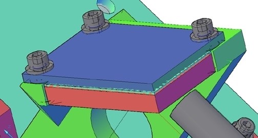
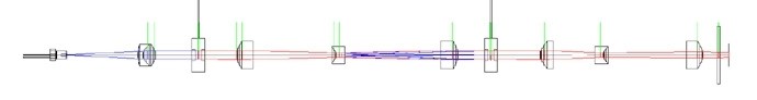
To wit: design an airborne optical image correlator.  Stabilize hyper-spectral imagers.  Design aircraft structural-optical windows.  Analyze detector cool-down times.  Test metal-foil optical elements.  Design nanometer-class alignment mechanisms.  Minimize the thermal impedance in a laser cavity.  Co-invent an infrared scanner.  Stabilize a gas-dynamic laser cavity.  Analyze thermal instability in lithographic lenses.  Establish intellectual property rights in cinematographic lenses.  Analyze dynamic stability of a free-space laser-com system.  Design a stand-off optical vibrometer system.

I’ve written about many of these at one time or another.  But another big interest today seems to be, “Where do AEH’s jobs come from?”  Well how about Barrington, Huntsville, Albuquerque, Carson, Dallas, St. Louis, Corona, Seattle, Palo Alto, Princeton, Los Angeles, Rochester, Tucson, Anchorage, San Diego, Linthicum, Mountain View, North Hampton, Azusa and, yes, even in Pasadena it’s been optomechanical engineering that AEH has done.

However you need help, wherever you need help AEH is there

N’Blarney ‘ere, b’Gorah!

Al H.
3-4-15

Optomechanics – The Calibrated Thumb Technique

Colleagues:

One of my early bosses, Wilford, introduced me to the “calibrated thumb” technique.  The immediate challenge was to anticipate static deflections and resonant frequencies in new design work.  His broader purpose was (I have since come to think) to open my mind about ways to develop my estimating skills.  I was working in airborne IR countermeasures at the time. 

I’ll introduce the technique to you with a much more recent example. 

I had been called in to make dynamic boresight stability analyses for a multi-sensor suite.  It was presented to me as an all-up finite element solid model of the system with three million-plus degrees of freedom.  I incorporated Ivory’s optomechanical constraint equations to calculate the line-of-sight errors for each sensor and the boresight errors between them.  This unified optomechanical model passed the rigid-body checks and static gravity checks just fine.  The calculated boresight errors were small compared to the specification. 

But I had an uneasiness.  There are lots of places in complex models to enter typos, select the wrong property from a long list or drop some decimal places.  How can I settle my uneasiness about someone else’s model?  My client had been around a while and done a lot of good stuff in the past, so I got an idea.

I went out to their shop where a variety of similar sensor systems were sitting on granite surface plates.  I got a height gage with a digital indicator and set it next to one of the systems.  Then I pushed on the system with my thumb applying what I thought to be about 1.0 pound and observed the deflection under the digital indicator’s tip.  I repeated it with two other sets of hardware in the shop.  The deflections were all somewhat different.  That was expected since the systems were of substantially different sizes.  But they’d all been designed and built by this organization.

Then I did a thought experiment, “If I push on the unified model with my thumb how much deflection should I expect?”

I went back to my computer and applied a similar load to the model.  The computed response compared well to my thought experiment.  My anxiety eased and the model proved, in test, to be reasonably accurate.  Whew!

A calibrated thumb is a good thing to have.  Thanks, Wilford.

Of course, my calibrated thumb is one of the tools I try to keep sharp.  When I got back to my home office I checked my thumb with a postal package scale.

Use it or loose it!

Al H.
1-29-15

Optomechanics – What do Optomechanics do all day?

Colleagues:

What does the optomechanical engineer bring to the table?  Hmmm…

A  few months ago a structural engineer friend asked me to analyze the strength of a lens assembly that he didn’t feel comfortable with.  It was injection-molded plastic, elastomeric rubber and glass.  OK…

Before that an optics friend challenged me to explain why it might be OK to mount glass lenses between threaded aluminum rings.  So, I did, but it took a while…

Another optics friend got me involved in resolving intellectual property disputes for mechanisms in cinematography lens assemblies…

Then a mechanical engineer friend needed a mass properties trade-off study between BK7 and sapphire for an airborne surveillance window…

Then another optics friend inquired about the possibility of nanometer-class structural actuators for 30 degrees K space optics.  So I designed, built and tested a successful set of them…

And before that I was asked to rationalize the structural damping coefficients to be used in an optical image jitter analysis.

The optomechanical engineer thinks outside the box.  He needs to work outside the box as well. 

Actually, I got that backwards:  He needs to work outside the box in order to be able to think outside the box.  It’s the peculiar demands, outside of his art, placed on the mechanical engineer by optics that inspire in him the intellectual curiosity to find workable engineering solutions.

Besides, he gets to enjoy your occasional company, too.  Thank you.

And, don’t forget to submit your abstract for “Optomechanical Engineering 2015.”
Assure your position in the program now:
         http://spie.org/OPO/conferencedetails/optomechanics
Hmmm… which one should I submit? 

Al H.
12-1-14

Optomechanics – How to Design with Ivory

Colleagues:

When performance is crucial the engineer uses tools to assure it.  Let me show you:

Say, we need a hyperspectral design with a 60 cm entrance pupil and stabilized to less than 15 ur, rms, LOS error in object-space.  We have the physical prescription.  How to get started?

The first thing I do is run the physical prescription data through AEH/Ivory Optomechanical Modeling Tools and import them into MSC/Patran-Nastran to start a system model (1).  The pink lines represent the optics and the yellow lines are structural bar elements with lumped masses. 

It’s a crummy “visual” but a very important first step.  I validate the model with rigid-body checks.  Then I run the model through random vibration adjusting the properties of the bar elements (areas, inertias, materials, etc.) until AEH/Ivory-in-Nastran satisfies the LOS performance requirement (12.3 ur, rms, in this case) with a reasonable combination of properties.

(1) 12.3 ur, rms
(2) 12.8 ur, rms
(3) 11.9 ur,rms
(4) 12.7 ur, rms

Next I incorporate solid models of the optical elements and replace the simple bars with more complicated beam elements (rectangular and circular tubes, some tapered) and optimize their wall thicknesses to maintain the AEH/Ivory-in-Nastran LOS performance (2).  I now have an estimate of a housing geometry (masses, dimensions, thicknesses) that will meet the LOS performance. 

The CAD engineer has decided on a three-piece housing design; an objective, a compound elbow and a detector.  The first section we develop is the compound elbow that holds the grating.  The CAD engineer makes a model which I import into the system model.  When we have an elbow design that maintains the AEH/Ivory-in-Nastran LOS performance in the system model, (3), we move ahead.

We design the objective and the detector sections next, import them, one at a time, into the system model.  We run the model through random vibration adjusting properties to maintain the AEH/Ivory-in-Nastran LOS performance before proceeding.  Finally, (4), we have developed a three-piece optical housing design through an iterative engineering process that supports the required LOS stability.

That’s optomechanical engineering with tools.  No surprises.  No excitement.  Just getting where we need to go, working from the optical prescription.

Now, to play a little…

Oh!  Joyous Summertime.

Al H.
7-7-14

Optomechanics – Preventing Failure

Colleagues:

As an engineer I’m absorbed with understanding the ways that things fail.

It is often said that an engineer’s job is to make things work.  Well, that’s nice.  Tinkerers can do that too.  The fact is that success rarely rewards an engineer while a single failure can nearly ruin him.  What’s really needed from an engineer is to make things work every time.  That’s a little different discipline.

Just ask Ray DeGiorgio, the GM engineer who’s taking the fall for the Chevy Cobalt ignition switch problem; or de Haviland, which nearly aborted the jet age, when a number of it’s Comet model passenger transports very quietly disappeared from the sky, without a trace; or the engineer who messed up the metrology on the Hubbell primary mirror.

So, as an engineer, I study how things fail in order to know how to prevent bad things from happening.

One key to failure prevention is early detection of possible failure modes.  In optical systems, virtually all optical failures result from some defect in the mechanical implementation.  These problems are never corrected by changing the optical prescription.  (Well, almost never:  There was the Hubbell primary mirror fix.)

Early detection requires special tools for the engineer.  To detect optical problems the optics and the mechanics must be coupled by the engineer from the moment of conception.  The results of this early coupling may only be estimates, but they’re essential.  Few early engineering estimates provide elegant eye-candy, and to some people they may not be persuasive.  But they give the engineer a sense of how to guide the design to the desired…, no, to the required destination.  The estimates will be refined and formalized as the design matures and eventually may become deliverable analyses.

The tools the engineer uses must be able to grow with the project from early conceptual estimates to the final NASA, DOD or NTSB reports, a continuous flow of engineering evaluations using the same proven techniques with demonstrable quality within a growing database of design detail as the project progresses.

That’s AEH’s mission and that’s why I study the way things fail. 

And that’s why I’m going to have a terrific Summertime!

How about you?

Al H.
6-27-14

Optomechanics – Keep Your Tools Sharp

Colleagues:

If spherical surfaces didn’t make pretty good images our optical industry would be entirely different.  As befits a technology that basically works as intended, cliches and rules-of-thumb perform a yeoman’s service.  And they work!  I’m glad that many of you enjoyed my parable about “kinematic” mounts.  Well, that is, they work until they don’t, as in that misunderstanding between the laser physicists and the mechanical engineers.  Thanks for all of your comments.

More recently I’ve been inspired by some of my students to publish the optomechanical influence coefficients of diffraction gratings (i.e., the ratios of a spectrum’s motions to the grating’s motions).  Gratings are often simulated as mirrors.  But the grating’s influence coefficients differ slightly from the mirror’s and there are more of them.  I’ll present my results in Mark Kahn’s conference, “Optical Modeling and Performance Predictions VI,” at SPIE’s meeting in San Diego this August. 

Imaging spectrometers (using gratings of course) are particularly challenging to the optomechanical engineer because the images of both the far-field object and the near-field slit (the spectrum) need to be stabilized simultaneously on the detector plane.  The slit operates as a field stop and the two images behave somewhat (and sometimes importantly) differently.  “Mining” the resulting “data cube” requires close registration between the spectrum and the far-field object’s image.  The grating will work in my Ivory Optomechanical Modeling Tools software.

In San Diego I’ll also present a paper in my own conference, “Optomechanical Engineering 2013.”  This presentation will describe the use of my Jade Optomechanical Modeling Tool.  Jade models the subsurface cracks induced by grinding and polishing.  I use it to engineer, for structural safety, components made of glasses, ceramics and other brittle materials.  As an example I’ll show how I applied Jade to meter-class optical windows for a civilian transport-class aircraft.  The windows have been in service for years.

Engineers develop tools to keep themselves out of trouble.  In the public works domain these have developed into codes and standards that engineers are obligated (by their insurance companies) to follow.  Elsewhere, engineers develop tools for themselves.  In optomechanical engineering there are few rules of thumb to help.  There are, however, a few cliches. 

Summer is coming!  Get out the sunscreen and water skis again!

Keep your tools sharp and your wits even sharper.

Hasta luego, caimán.

Al H.
6-18-13

Optomechanics – Elastomeric Mounting of Mirrors

Colleagues:

Please allow me to complete the discussion of my engineering tool for elastomeric mounting of mirrors.

So, according to my previous missive, the elastomer reduces the shear stresses on the back face of the mirror by two to three orders of magnitude compared to a rigid adhesive.  That’s all well-and-good but how do we know that it’s good enough?  Of course those of you who have picked up the source reference (SPIE: 6665-03, 2007) know the answer.  You also know why there are no dimensional quantities (inches, millimeters, etc.) for the mirror in my equation,

In the derivation I assumed that the gravitational sag of the mirror was a reasonable budget for the figure errors induced by the mounting method.  When I equated the deflection of the mirror due to gravity to the deflection of the mirror due to the thermally induced shear stresses on the back of the mirror the mirror’s dimensions (thickness and edge length) dropped out leaving only the adhesive’s thickness, t, the environmental temperature change, DT, the difference in coefficient of thermal expansion between the mirror and the mount,   Da , the modulus of rigidity (shear modulus) of the elastomer, G, and the specific weight of the mirror substrate, sVoila!


So, that’s my engineering tool.  But plugging numbers in is the easy part.  Now the engineer has to go to work.  You’ll find a discussion of the engineering considerations in the source reference also.

Thank you for your patience. 

‘Tis mid-winter and Valentine’s day is nigh.  Ah, the joy of good company!  Thank you all, again. 

Yes Tiny Tim, thank you too.

Al H.
2-6-12

Optomechanics – Adhesive Mounting of Mirrors

Colleagues:

Let me revisit my engineering tool for adhesive mounting of mirrors:

Those of you who have studied the source reference (SPIE: 6665-03, 2007) know now that it guides the engineer to elastomeric adhesives for the mounting.  The reason for this is that hard adhesives have a high modulus of rigildity, G. This fact leads to large optical distortions of the mirror surface due to differential thermal expansion and contraction between the mirror and the mount.  But, for elastomers their low modulus of rigidity tends to isolate the mirror from the differential expansion and contraction of the mount.  The reduction in surface distortion may be a factor of between two to three orders of magnitude using an elastomer compared to a hard adhesive.

Simultaneously, Poisson stiffening tends to stabilize the position of the mirror’s surface.  It increases, by a similar factor of 100 to 1,000, the apparent tension/compression modulus, K‘, of the elastomer between the mirror and the mount (comparing K’ to the Young’s modulus, E).  The bulk modulus, K, for a silicone elastomer is typically in the range of 150,000 psi to 200,000 psi whereas its modulus of rigidity may be as low as 180 psi to 200 psi.  In thin adhesive layers the apparent tension/compression modulus, K’, approaches the bulk modulus, K.  Since the Young’s modulus would be about 570 psi, which becomes a Stiffening Factor of about 300 (see above).  The low modulus of rigidity assures small shear stresses in the bondline due to thermal expansion and contraction while the high bulk modulus stabilizes the mirror’s surface in the optical path.

Perhaps you begin to see why this tool is really not a rule-of-thumb.  It is an engineering technique for tailoring the thickness, t, of a specific elastomeric adhesive, G, to the properties of the mirror, the properties of the mount and the thermal environment the assembly will see in service.  It also requires the engineer have some understanding of the Poisson stiffening effect in thin bondlines.

I hope the Holidays left you all refreshed and eager for the New Year.  Here we go again!

Al H.
1-10-12

Optomechanics – Minimum Adhesive Thickness

Colleagues:

Wherever I visit, rules-of-thumb are a hot button topic these days.  My normal response has been that engineers are expected to do better than use rules-of-thumb.  But Fall is here and the Holidays are close-at-hand, so allow me to be a little more responsive this time. 

I develop engineering tools and skills to support and guide my engineering interests.  For instance, I have developed techniques to analyze the surface figure errors introduced by element mounting techniques.  In the spirit of the coming Season, I will give to one and all (yes, even to Tiny Tim) one of my engineering tools:

It tells the engineer the minimum adhesive thickness necessary to limit the thermal distortion of a mounted mirror.  It is easier to use than a finite element code and probably more accurate.

I do not, myself, consider the above expression a rule-of-thumb but rather one of several engineering tools for use in these kinds of problems.  The curious may read my original paper, SPIE: 6665-03, 2007.  The expression is formed by substituting equation (6) into equation (10), both from the subject paper.  I hope you find it as useful as I have.  It’s about as close as I get to a rule-of-thumb in my practice.

Now, let us turn to the approaching Season:  The Joyous, Tumultuous, Boisterous, Extravagant Holiday Season from All-Hallows Eve to Twelfth-Night.

We can talk about engineering tools, and rules-of-thumb, any old time.

We should Enjoy and take Cheer Now!

Al H.
10-24-11