Optomechanics – Using CodeV Prescription in Ivory and Jade to Find Structural and Thermal Weaknesses

Colleagues:

I’ve been known to lecture my students and colleagues on the need to keep their tools sharp.  Some time ago AEH was invited to a design review as an observer and since I had no direct participation I sat at the back of the room, behind John, the systems engineer who was controlling the projector.  The technical sessions went well but about half-way through the schedule and budget sessions he suddenly blackened the screen and turned on the overhead lights.  He slowly turned and surveyed those of us sitting behind him.  His gaze settled on me!  “What, John?” I asked.  He stared at my hands which were holding my pen knife and its sharpening steel.  “Just keeping my tools sharp,” I declared sheepishly.

One of AEH’s sharpest tools, other than a pen knife, is Ivory’s Optomechanical Modeling Tools.  It’s been under continuous development incorporating many of my personal insights working as a mechanical engineer in the optics industry.  I recently put together an updated version and released it to all users of Version 3.  That’s another way I keep AEH’s tools sharp (and protect AEH’s Ivory subscribers, too).  Ivory is AEH’s prime tool for engineering thermally and structurally reliable optical systems.  It’s designed to work in both Excel and Nastran and its application early in the design process prevents much embarrassment and saves many labor-hours from preventable failures that may occur later in qualification tests and service.

Somewhat more recently AEH was invited to participate in a “Tiger-Team” review of a sub-contractor.  The initial issue was broken glass.  The first thing I did was get a copy of the physical optical 
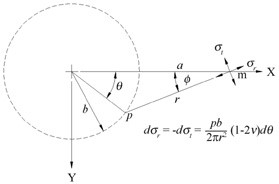
prescription (CodeV) and read it into Ivory (for the structure) and Jade (for the broken glass).  I could then quantitatively infer where the principal structural and thermal weaknesses might be.  With that insight I was able to form an independent assessment of the completeness of the design team’s engineering effort, which undergirded my report to the prime contractor.

I hope to see all of you at SPIE’s Optics+Photonics in San Diego come August.  I’ll be teaching (Optomechanical Analysis), chairing (The Optomechanical Engineering Technical Group and Optomechanics 2017), presenting and publishing (on a new diffraction grating capability in Ivory) and begin planning our next SPIE Conference (Optomechanics 2019). 

That also keeps AEH’s tools sharp. 

Hasta luego, caiman.

Al H.
6-5-17

Optomechanics – Poor Optical Performance is a Mechanical Problem

Colleagues:

Hey!  It’s been one Heck-of-a-Year…

…horrible images, tricky windows, cracked laser rods, soft adhesive, savvy clients, a challenge from the nanoradian and writing a book-and-a-half.  What’ll it be next?

Our industry is terrific fun.  Optics is an art that was just meant to work, until it doesn’t.  Then the solution is almost always mechanical:  a longer stroke on the focus mechanism; find a way to install a “corrector” lens; fold the system here or there; find a new adhesive; brace the objective doublet; stiffen the cold finger, control-grind and polish the edges, etc.

And that’s all as it should be.  Once the optical designer finishes his design it’s virtually impossible to improve it.  If that were not true the optical designer would probably not stay employed at the firm.  All deviations from the prescription are the mechanical engineer’s contribution.  Poor performance is therefore a mechanical problem; something is improperly located, dimensioned or deformed and the solution is also mechanical, correcting the mechanical engineer’s positional or dimensional specifications or stiffen the structure.

The errors are almost always detected after the system is assembled and that’s what makes it so much fun.  The mechanical engineer has to think ahead and analyze ahead to avoid the problems in that first assembly.

And that’s why we have a conference in San Diego this August with SPIE, to share with each other and our colleagues the discoveries and methods for making optical systems work in spite of it all!

Attached is the Conference Announcement.  Just click on “submit an abstract” on the bottom of the second page to reserve your position in the Program.

Look out 2017, here we come!

Al H.
12-28-16

Optomechanics – Bridging the Chasm

Colleagues:

Ah yes, there is a great deal to optomechanics! 

And so much of it is on the hairy edges of, slightly beyond, or in-between the academic disciplines that we study at the university.  The engineering challenge is to make it work anyway.  In my practice I refer to it as “Bridging the Chasm” or B/C.  It involves surveying both sides of the gorge between disciplines before building on them.  That’s just good engineering practice.  It almost falls into Systems Engineering… almost.

One example of B/C is a dialog I had a while ago with a dear friend who was concerned about the fracture of glass lenses mounted in metal compression rings.  Structural engineers were not interested in glasses.  The opticians were disinterested in elastic analysis.  I had to sit down and solve the differential equations of the problem myself (Proc. SPIE, 7424-09. 2009). 

They showed that the actual tensile stresses were four orders of magnitude smaller than those predicted by the traditional method (Delgado and Hallinan, Opt. Eng., 1975).  That “bridge” between the disciplines for metals and glasses has saved my clients’ buttons more than once. 

Another B/C example was a modification to an unstable EO weapon sight… but that’s enough about me

“The time has come,” the Walrus said, “to talk of many things…”

Yes, the great Optics+Photonics 2017 Roadshow (Symposium) is returning to San Diego this coming August and the Optomechanical Technical Group is organizing an exciting two-or-more day conference to highlight your accomplishments this past year.

You all have your own experiences and stories.  Bring them to your Optomechanical Engineering 2017 Conference.  It’ll be a great show!

“…of shoes and ships and sealing wax, of cabbages and Kings.”

Here’s hoping I’ll see all of you in San Diego come August, at least those who survive the Great Pumpkin.

Al H.
10-24-16

Optomechanics – Implementing Intentions

Colleagues:

Ok, ok.  I left you hanging.  But, in spite of that, a number of you offered your opinions ranging from the Hawthorne Method to Witchcraft!  It turns out that some of you studied Industrial Engineering while others studied Theology!  What a group.

Well, the engineering lesson I thought I learned (or actually re-learned) was,

“Just because it’s in the drawings doesn’t mean its in the hardware.” 

I cut my teeth as a Liaison Engineer in a factory fixing the butches that factory workers create when assembling airplanes at Boeing’s plant in Seattle.  That’s a whole different industry but whether it’s optomechanical or aeromechanical, the principle is the same:  Someone has to assure that the engineer’s intentions are implemented.  In our culture that task usually falls to the Quality Assurance organization.  Gene took up that challenge.  And, it felt just like Boeing’s factory, except for the photons.

Thank you for hanging-in-there with me.

Enjoy early Autumn.

Al H.
9-20-16

Optomechanics – How to Overcome Resistance from Management

Colleagues:

There is so much more to optomechanics than meets the eye (or ear or touch, even).  I learned a great optomechanical engineering lesson from a Quality Assurance engineer!

Gene was recruited (and offered a “bounty”) by a major manufacturer of lasers for printers to improve the quality of their products, ~1/3rd of which were failing in the 1,000 hour burn-in test.  Gene, in turn, called me in to supplement his electronics industry experience.  (Full disclosure:  We had worked together at one of our previous employers.)

We ran into resistance from both the Mechanical Engineering management and the Factory management.  The mechanical engineers would not let me “review or analyze” any of their design work and the factory would not let me “observe” their operations during working hours.  Hmmm….  Both Gene and I were dumbfounded.  But, I must say that Gene was a resourceful Devil.

He invited me to coffee at a nearby bistro and swore me to secrecy.  Then he laid out his plan:  He would dress me in a white QA smock, give me a clipboard, a jeweler’s loupe, a marking pen and spools of red, yellow and green adhesive dots.  I’d spend most of the day in his office but I’d go out to the factory floor on coffee breaks and lunch times.  I’d cruise the floor, stopping at empty work stations and pretend to inspect the stations, one at a time, applying the loupe and the colored dots (annotating a few, especially the red ones) while making notes on the clipboard.  At the end of each break I’d return to Gene’s office and hide-out.  It took about three days to cover each of the work stations twice.  Then he released me telling me to “disappear.”  I went back to AEH and made myself busy elsewhere.

The next I heard from Gene was a phone call from Norwood, Massachusetts.  The plan worked spectacularly, he had collected his “bounty,” left that company and moved with his family to more stable employment in Norwood.

The laser manufacturer is gone and I think Gene would approve of me sharing his secret with you now.

The lesson?  I think you got it.

Summer’s over and it’s downhill to the Great Pumpkin .  . Shhhhhhhhh!

Al H.
9-13-16

Optomechanics – Non-Structural Solid Mechanics

Colleagues:

I was in the Boston area recently to teach one of my day-long classes in optomechanics.  It was terrific to meet with an enthusiastic group of engineers.  I introduced them to a number of technical issues that they probably did not encounter in their college or university days.  One of those issues was “non-structural” solid mechanics.

There are aspects of the optomechanical design arts that fall into an academic “chasm” that lies somewhere between structural engineering and mechanical engineering.  Structural engineers study the behavior of “structural materials” that are thought to be safe for civil applications (office buildings, railroad bridges, aircraft).  Mechanical engineers may be introduced to the behavior of structural materials but also must study other topics such as machine design, heat and mass transfer, vibration theory and thermodynamics that are necessary to understand their industrial applications (automobiles, escalators, power generation). 

Optomechanical design often calls upon a variety of “civilly” un-safe materials (glasses and elastomers for instance) that may be incompletely characterized and not well understood or appreciated by either structural engineering (which tends to avoid them) or mechanical engineering (which may be largely unaware of their limitations). 

In my classes I attempt to bridge this chasm by introducing the available science for these non-structural materials.  The “strength” of glass is one topic and the “stiffness” of elastomers is another.  They make an interesting pair in that they both are considered “brittle” materials requiring some knowledge of fracture mechanics while elastomers may also require a large-displacement elastic theory which has never been fully developed.  Fun stuff.

Yes, rubber is a brittle material!

I look forward to seeing you in San Diego at the end of the month… and while you’re there don’t forget to drop by SPIE’s bookstore to peruse my new book, The Optomechanical Constraint Equations:  Theory and Applications.  I wrote it just for you.

See you all there!

Al H.
8-11-16

Optomechanics – Forensic Observation on Shock Test

Colleagues:

I was peering into the AEH archives the other day and got a shock.  I needed the source code that I use to analyze the effects of a variety of shock pulse shapes.  What I found was a complete set of mechanical engineering drawings for the medium-weight hammer blow shock test machine at the Hughes-Fullerton facility!  John Martin, who ran the test lab, gave them to me after AEH succeeded in getting a client’s Optical-Nav system qualified for Navy shipboard minesweeper service.

AEH’s job was to specify the shock isolators.  To understand the problem I had prepared a massive Nastran model of the system (6 feet high, two feet square and 550 pounds) mounted on an array of Aeroflex wire-rope isolators.  The numbers had said it should pass the shock test, but it failed.  AEH was called to the lab.  The bolts holding the isolators had stripped the threads in the isolator flanges!  I spent lunch-time with the Nastran output file reviewing the loads and forces and couldn’t make sense of the results.  The client thought that larger/stronger isolators were required.

I went back to the test lab and re-inspected the failed isolator mounts.  I found that the threaded ends of all the failed bolts were flush with the inside surface of their isolator flanges and that all of the un-failed bolt-ends protruded into that sway-space by about 3/16ths of an inch. 

I returned to the Nastran file, looking at displacements in stead of forces.  It predicted that the isolators would use virtually all of their sway-space.  The failed bolts had actually been pushed out when the isolators prematurely bottomed on the bolt-ends, not pulled out when the isolators stretched to their limits.  The bolts were too long.  Larger isolators were not necessary.

One fix was to put extra flat washers under the heads of the bolts so their ends would not protrude into the sway-spaces.  With that accomplished we returned to test the next day and PASSED!

That was AEH’s second successful adventure in John’s shock-test lab.  He graciously offered AEH the drawings for his test machine and invited me to present a paper at the annual conference of the Institute of Environmental Sciences, of which he was President.  I accepted both.

Engineers need to keep their forensic skills sharp, too!

Thank you John Martin!

Al H.
6-1-16

Optomechanics – An Engineer’s Tactile Sense

Colleagues:

It’s 2016 so, here we go….

For starters, I moved the AEH offices again.  See the new contact info below. 

Now, I’ve told you the story about the number of rivets in the Queen Mary.  Well here’s one about my calibrated thumb.

Early in my career my boss, Wilford, invited me to the environmental test laboratory.  We found a space payload mounted on the shake table.  He turned to me and asked, “What’s the fundamental resonant frequency of this beast?”  I turned to go up to the Structures Department but Wilford called me back.  He said something like, “We’re the mechanical engineers and should be able to get a pretty good handle on this right here.”

Wilford asked me, “How much do you think it weighs?”  I estimated the dimensions, studied the construction and made a guess.  He raised an eyebrow, but nodded.

Then Wilford walked around the payload and pressed on it several places then beckoned me over suggesting I press on it, which I did.  He asked how much it had moved.  I hadn’t noticed the motion so I pressed again and told him how much motion I had observed.  He asked how hard I had pressed but I had no idea.  He took me to the Inspection Department and had me push on the scales with the same force I’d pushed on the payload.

We went back to Wilford’s office and on his whiteboard he wrote “2 x pi x f = (k/m)^.5,” “k = force/motion” and “m = weight/gravity.”

The next day the test engineer reported that Wilford’s resonant frequency estimate, f, was 3% high.  Not bad.

My estimate wasn’t as good as his but I learned a lesson:  It’s useful for an engineer to maintain a tactile sense of the magnitudes of forces.  I cater to my right thumb.  What about you?

One more tool to keep sharp in 2016.

As I said up-top… “Here we gooooooooo!”

Al H.
1-5-16

Optomechanics – Completing the Zemax Prescription with Ivory

Colleagues:

Well, I’m just back from a week in San Diego for SPIE’s Optics+Photonics meeting.  WOW!  Everybody seems to have some way to “model” optomechanical behavior but nobody seems to know how to verify that the results are right.  That’s why I created “Unified Modeling” (the Ivory and Ebony Optomechanical Modeling Tools):  to provide the engineer verifiable confidence in the results. 

A good friend of mine likes to declare “You need to know the answer before you do the analysis!”  Cute, huh?  It always goes over well from the back of the room during a CDR.  Well, the next-best-thing (I have found) is to have used the same procedures and theories to analyze a case (any case) for which you already know the answer.  One of my favorite test cases is called a “six degree of freedom rigid body check.”  You put the model through three translations (X, Y and Z) and three rotations (Rx, Ry and Rz).  In optical systems it’s easy to predict the image motions on the detector.  They’re either 1.0, computational zeros or some predictable fraction of the back image distance.  And, you don’t need a finite element code.  You can do it all in a spreadsheet.

AEH analyzed the stability of a hyperspectral sensor.  Our client provided the optomechanical influence functions based upon the Zemax optical design.  The random analysis showed that the image stability was out of specification by an order of magnitude.  A subsequent six degree of freedom rigid body check showed large values in stead of computational zeros.  A review of the influence functions showed that they were incomplete.  AEH put the Zemax prescription into Ivory to get a complete set of influence functions.  This six degree of freedom rigid body check showed computational zeros across the board in a spreadsheet!  And subsequent Nastran random stability analysis predicted the performance would be within specification.  Which it ultimately proved to be during qualification testing.

Unified modeling provides traceable modeling performance and helps to keep an engineer’s tools sharp.

School starts next week.  Good luck to all the children!

Al H.
8-21-15

Optomechanics – Some Stuff AEH Built

Colleagues:

Every once in a while we at AEH get a chance to get our hands dirty.  You know, build stuff, install stuff, test stuff, fly stuff…  Here’re a few examples.  The first is a “cryogenic” vacuum test facility for qualification and acceptance testing of ISR focal plane arrays.  AEH designed, built and delivered them to fit into the client’s LN2 bell jar system.

The second is an airborne, gimbal mounted, spectrometer for environmental studies over the Arctic Ocean during mid-winter.  A team at AEH designed and built the gimballed sensor system, installed it (in Alaska) into the flight vehicle (a helicopter) and got FAA certification to fly the system in civil airspace.

Then there are the submicroradian-class adjustable (set-n-forget) fold mirrors for ultra-precise alignment of wavefront bundles.  No cold “weather” here, just high altitudes and awesome vibrations.

AEH is known primarily for analysis, but it’s the non-linear stochastic process of synthesis (better known as design) that makes it all work.  That’s engineering.

I’ll be expanding on this topic in a couple of papers next month at Optics+Photonic in San Diego.

It’s all great fun!

Al H.
7-7-15