Optomechanics – Non-Structural Solid Mechanics

Colleagues:

I was in the Boston area recently to teach one of my day-long classes in optomechanics.  It was terrific to meet with an enthusiastic group of engineers.  I introduced them to a number of technical issues that they probably did not encounter in their college or university days.  One of those issues was “non-structural” solid mechanics.

There are aspects of the optomechanical design arts that fall into an academic “chasm” that lies somewhere between structural engineering and mechanical engineering.  Structural engineers study the behavior of “structural materials” that are thought to be safe for civil applications (office buildings, railroad bridges, aircraft).  Mechanical engineers may be introduced to the behavior of structural materials but also must study other topics such as machine design, heat and mass transfer, vibration theory and thermodynamics that are necessary to understand their industrial applications (automobiles, escalators, power generation). 

Optomechanical design often calls upon a variety of “civilly” un-safe materials (glasses and elastomers for instance) that may be incompletely characterized and not well understood or appreciated by either structural engineering (which tends to avoid them) or mechanical engineering (which may be largely unaware of their limitations). 

In my classes I attempt to bridge this chasm by introducing the available science for these non-structural materials.  The “strength” of glass is one topic and the “stiffness” of elastomers is another.  They make an interesting pair in that they both are considered “brittle” materials requiring some knowledge of fracture mechanics while elastomers may also require a large-displacement elastic theory which has never been fully developed.  Fun stuff.

Yes, rubber is a brittle material!

I look forward to seeing you in San Diego at the end of the month… and while you’re there don’t forget to drop by SPIE’s bookstore to peruse my new book, The Optomechanical Constraint Equations:  Theory and Applications.  I wrote it just for you.

See you all there!

Al H.
8-11-16

Optomechanics – Membrane Properties

Dear Colleague:

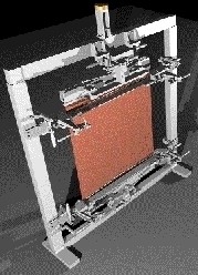
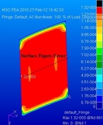
AEH tested, with a client, the ability of metal foils and polymer films to form membranes with optically useful surfaces such as cylindrical conic sections (SPIE:  5494-50, 2004).  AEH subsequently explored the concept using non-linear structural solution sequences in MSC/Nastran. 

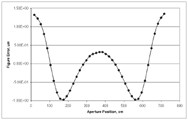
AEH’s study identifies trade-offs among the material properties, dimensional properties, initial conditions and loading.  It also provides the optomechanical engineer design tools to minimize the surface figure errors in real, non-idealized, clear apertures.  For instance, compensate for defects in the membrane such as non-uniform thickness, variable properties and non-planar initial membrane shapes.

AEH:  Cutting-edge engineering for cutting-edge systems.

Al H.
2-28-12

Optomechanics – Elastomeric Mounting of Mirrors

Colleagues:

Please allow me to complete the discussion of my engineering tool for elastomeric mounting of mirrors.

So, according to my previous missive, the elastomer reduces the shear stresses on the back face of the mirror by two to three orders of magnitude compared to a rigid adhesive.  That’s all well-and-good but how do we know that it’s good enough?  Of course those of you who have picked up the source reference (SPIE: 6665-03, 2007) know the answer.  You also know why there are no dimensional quantities (inches, millimeters, etc.) for the mirror in my equation,

In the derivation I assumed that the gravitational sag of the mirror was a reasonable budget for the figure errors induced by the mounting method.  When I equated the deflection of the mirror due to gravity to the deflection of the mirror due to the thermally induced shear stresses on the back of the mirror the mirror’s dimensions (thickness and edge length) dropped out leaving only the adhesive’s thickness, t, the environmental temperature change, DT, the difference in coefficient of thermal expansion between the mirror and the mount,   Da , the modulus of rigidity (shear modulus) of the elastomer, G, and the specific weight of the mirror substrate, sVoila!


So, that’s my engineering tool.  But plugging numbers in is the easy part.  Now the engineer has to go to work.  You’ll find a discussion of the engineering considerations in the source reference also.

Thank you for your patience. 

‘Tis mid-winter and Valentine’s day is nigh.  Ah, the joy of good company!  Thank you all, again. 

Yes Tiny Tim, thank you too.

Al H.
2-6-12

Optomechanics – Adhesive Mounting of Mirrors

Colleagues:

Let me revisit my engineering tool for adhesive mounting of mirrors:

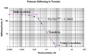
Those of you who have studied the source reference (SPIE: 6665-03, 2007) know now that it guides the engineer to elastomeric adhesives for the mounting.  The reason for this is that hard adhesives have a high modulus of rigildity, G. This fact leads to large optical distortions of the mirror surface due to differential thermal expansion and contraction between the mirror and the mount.  But, for elastomers their low modulus of rigidity tends to isolate the mirror from the differential expansion and contraction of the mount.  The reduction in surface distortion may be a factor of between two to three orders of magnitude using an elastomer compared to a hard adhesive.

Simultaneously, Poisson stiffening tends to stabilize the position of the mirror’s surface.  It increases, by a similar factor of 100 to 1,000, the apparent tension/compression modulus, K‘, of the elastomer between the mirror and the mount (comparing K’ to the Young’s modulus, E).  The bulk modulus, K, for a silicone elastomer is typically in the range of 150,000 psi to 200,000 psi whereas its modulus of rigidity may be as low as 180 psi to 200 psi.  In thin adhesive layers the apparent tension/compression modulus, K’, approaches the bulk modulus, K.  Since the Young’s modulus would be about 570 psi, which becomes a Stiffening Factor of about 300 (see above).  The low modulus of rigidity assures small shear stresses in the bondline due to thermal expansion and contraction while the high bulk modulus stabilizes the mirror’s surface in the optical path.

Perhaps you begin to see why this tool is really not a rule-of-thumb.  It is an engineering technique for tailoring the thickness, t, of a specific elastomeric adhesive, G, to the properties of the mirror, the properties of the mount and the thermal environment the assembly will see in service.  It also requires the engineer have some understanding of the Poisson stiffening effect in thin bondlines.

I hope the Holidays left you all refreshed and eager for the New Year.  Here we go again!

Al H.
1-10-12