Colleagues:
I mentioned earlier that there is a great deal to optomechanics. Even
full time practitioners can lose track of the current scope of the
optomechanical arts. And with a well corrected optical design the onus
falls to the optomechanical engineer “to make it all play.”
I was working with another dear friend shortly ago. He was contemplating
a compound hyper-spectral imaging system and wondered if I knew anyone who
could help stabilize the instrument. Of course, I immediately raised my
own hand. He said that I didn’t understand: The entire image plane
had to stay in strict alignment over the entire detector array all the time.
He behaved incredulously but, generously, heard me out.
I explained: AEH’s Ivory Optomechanical
Modeling Tools operate over the entire exit window
(field-of-view on the image plane, if you prefer). They tell the
optomechanical engineer what’s going on at the edges, the corners and the
center or anywhere else in the image. The Tools
can do this because their Optomechanical Constraint Equations determine
the alignment of the entire image plane (position, orientation and size) over
the entire detector array. He said, “Show me.”
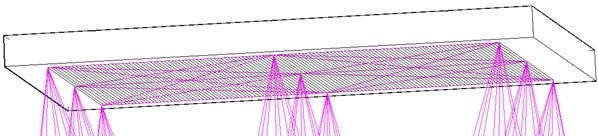
So, I used the Ivory OMT to model the image’s corners, edges and center in shock, vibration and thermal environments. Initially the image’s stability over the entire detector array was barely marginal. But with a little tweaking of the structural design, informed by the influence coefficients from Ivory, we got it within specification with a comfortable margin. This system flies today with confidence.
Just Bridging the Chasm one more time.
I hope you all enjoyed a Great Thanksgiving. It’s down-hill from here to 12th-night!
Cheers.
Al H.
11-29-16