Optomechanics – SOLVED: Elastic Theory’s Differential Equations for the Tensile Stresses in Glass Lenses Mounted in Threaded Metal Rings

Colleagues:

AEH has solved elastic theory’s differential equations for the tensile stresses in glass lenses mounted in threaded metal rings, and it’s good news.

Paul Yoder had originally proposed Delgado and Hallinan’s 1975 solution (Opt. Eng. 14) but their solution gave very high tensile stresses in the lenses, high enough that virtually all such lenses should have fractured.  None of my ring mounted glass lenses had ever suffered that fate.  I surveyed a number of my colleagues and none of them recalled a ring mounted glass lens fracture.

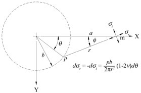
Delgado and Hallinan’s work was flawed.  To correct their flaw would require a new solution to the equations of elasticity that honored the appropriate contact geometry.  AEH finally made it happen and the result is surprisingly simple,

s = p(1-2u)/b,

where s is the peak tensile stress, p is the linear ring load, b is the radius of the contact ring and u is the Poisson’s ratio of the glass.  This stress is three-to-four orders of magnitude lower than that predicted by Delgado and Hallinan.

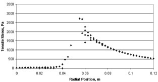
Using Nastran AEH was also able to verify the general shape of the stress distribution in spite of Nastran’s notorious difficulty at the point of load application.
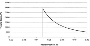

Closed-form solution       >>>         Nastran solution

To learn more you have choices:  Either download AEH’s peer reviewed paper from SPIE [Optical Engineering 57(5), 055105] or go through the gory details with me in my tutorial,

“Optomechanical Analysis,”
SPIE’s Optics and Photonics Symposium in San Diego
8:30 AM to 5:00 PM on the 21st of August.Cheers!

Al H.
6-6-18

Optomechanics – Recommended Reading

Colleagues:

Joy to all, and thank you for your awesome support of our Optomechanical Engineering 2017 Conference in August.  Just wait ’till you see the program.

Now, back to business.  Fractures in glass optics seem ubiquitous. 

So… the optomechanical engineer has a problem.  He’s nominally responsible for protecting the glass elements in the optical systems he designs.  But there’s very little (if any) information available on the structural properties of the glasses that optical designers specify.  And the guidance for the engineer on using the available data is all-over-the-map, from the incomprehensible to the impossible.  No wonder most engineers use simple “rules-of-thumb.”

That’s where I started, “Keep the tensile stresses under 2,000 psi.”  But then the glass broke anyway!  So I started testing the glass objects to 4,000 psi.  I broke a few in testing but those that went into service are still in service, as far as I know.  I didn’t get to make many, they were too big and heavy.  A colleague who specialized in space-based ISR systems confided to me that he kept the stresses under 500 psi!  That’s when another colleague gave me a copy of “Reconnaissance and Surveillance Window Design Handbook” (AFAL-TR-75-200). 

Voila!  Section 7.3.1 is the perfect introduction for the engineer to “Allowable Stresses in Glass.”  It covers fabrication process controls, slow crack growth through stress corrosion (from moisture) and estimating the service life by integrating the stress corrosion equations for eight glasses.  The Wizard’s green curtain is drawn back disclosing all of his secrets and Dorothy dances down the yellow brick road and back to safety in Kansas.

Every optomechanical engineer needs a copy of that Handbook to help him protect the optical glass that has been entrusted to him by the optical designer.  It guides the design, analysis and fabrication of glass optical elements.  Perhaps the engineer should enter the required structural properties, including the fracture toughness and stress corrosion constants, on the lens drawings (think the yellow brick road).  The Handbook’s drawback is that only eight glasses are treated and some of those have since been re-formulated to remove toxic elements.

The glass suppliers also need copies of the Handbook so they’ll know what the engineer is requesting and, maybe someday, put the information in their glass catalogs and data sheets.

Joy!  Spring is just around the corner.  Ahh… Kansas in Springtime!

Al H.
3-10-17

Optomechanics – Bridging the Chasm

Colleagues:

Ah yes, there is a great deal to optomechanics! 

And so much of it is on the hairy edges of, slightly beyond, or in-between the academic disciplines that we study at the university.  The engineering challenge is to make it work anyway.  In my practice I refer to it as “Bridging the Chasm” or B/C.  It involves surveying both sides of the gorge between disciplines before building on them.  That’s just good engineering practice.  It almost falls into Systems Engineering… almost.

One example of B/C is a dialog I had a while ago with a dear friend who was concerned about the fracture of glass lenses mounted in metal compression rings.  Structural engineers were not interested in glasses.  The opticians were disinterested in elastic analysis.  I had to sit down and solve the differential equations of the problem myself (Proc. SPIE, 7424-09. 2009). 

They showed that the actual tensile stresses were four orders of magnitude smaller than those predicted by the traditional method (Delgado and Hallinan, Opt. Eng., 1975).  That “bridge” between the disciplines for metals and glasses has saved my clients’ buttons more than once. 

Another B/C example was a modification to an unstable EO weapon sight… but that’s enough about me

“The time has come,” the Walrus said, “to talk of many things…”

Yes, the great Optics+Photonics 2017 Roadshow (Symposium) is returning to San Diego this coming August and the Optomechanical Technical Group is organizing an exciting two-or-more day conference to highlight your accomplishments this past year.

You all have your own experiences and stories.  Bring them to your Optomechanical Engineering 2017 Conference.  It’ll be a great show!

“…of shoes and ships and sealing wax, of cabbages and Kings.”

Here’s hoping I’ll see all of you in San Diego come August, at least those who survive the Great Pumpkin.

Al H.
10-24-16

Optomechanics – Membrane Properties

Dear Colleague:

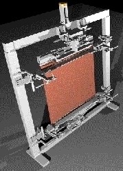
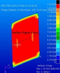
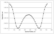
AEH tested, with a client, the ability of metal foils and polymer films to form membranes with optically useful surfaces such as cylindrical conic sections (SPIE:  5494-50, 2004).  AEH subsequently explored the concept using non-linear structural solution sequences in MSC/Nastran. 

AEH’s study identifies trade-offs among the material properties, dimensional properties, initial conditions and loading.  It also provides the optomechanical engineer design tools to minimize the surface figure errors in real, non-idealized, clear apertures.  For instance, compensate for defects in the membrane such as non-uniform thickness, variable properties and non-planar initial membrane shapes.

AEH:  Cutting-edge engineering for cutting-edge systems.

Al H.
2-28-12

Optomechanics – The Journal of Applied Remote Sensing

Colleagues:

It was a great gathering in Orlando last month: conferences, classes, banquets and above all friends.

I was invited to address a meeting of engineers whose topic was “Acquisition, Tracking, Pointing, and Laser Systems.”  I sat in a dark room staring at a bright screen and listened for two hours to electrical engineers talk about stabilizing lines-of-sight.  They all showed amazing slides of flow diagrams and control systems:  resolvers, torquers, Bode plots, gyros, transfer functions, encoders, phase margins, accelerometers, amplifiers, feedback loops, etc.  Not one single slide showed a line-of-sight, an optic, a laser beam or a target

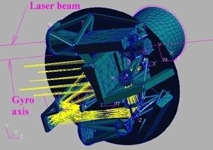
I was last on the agenda.  I opened by pointing out that lines-of-sight and laser beams were real physical features, just as real as the axis of rotation of a gyro.  Then I demonstrated a way to link the lines-of-sight of imagers and lines-of-propagation of lasers to inertial sensors through elastic behavior of finite element models.  Then I showed an analysis in which the rms error between the gyro and the laser was about twice as big as the gyro’s rms error itself.  “Was the laser-to-gyro error in their budget,” I asked, “or in the optical designer’s?”  “What about the imager-to-gyro error?”  The audience seemed to have some difficulty answering my queries and also some framing their own, but they were very gracious.  We shook hands and then, suddenly it seemed, I was outside standing in the warm Spring afternoon sunlight.  Perhaps I’d been impertinent. 

A week or so later, back in the office, I received an invitation from the engineers to publish my remarks in their prestigious journal, The Journal of Applied Remote Sensing.  I guess I was not too impertinent.  It’s a fine balance;  someone has to identify the possibility, tickle the imagination, “stir the pot” and, sometimes, “serve the first dish”.  I’ve accepted this invitation too.

I have one relic from the event to commemorate it.  That’s the slide of mine showing a laser beam and an IR imager coupled to a gyro’s axis of rotation through a finite element structural model of a sensor suite.

It was in deed a great gathering in Orlando last month.  And, ahh… the friends!  Thank you all.

Now…  Summer is nigh.  Get out the sun-block and water skis.

Enjoy!

Al H.
5-31-11