About the Rubicon Single and Dual Stage Actuators
The Rubicon actuator resulted from a competition that was initiated by NASA. In 1996 the Langley Research Center let four contracts for development of actuators suitable for deformable mirror applications. The Rubicon actuator was the only one to complete its testing and deliver a prototype device along with the final report1. Figure 1 shows the
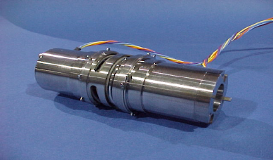
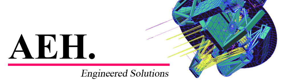
Figure 1. Initial Rubicon prototype actuator.
prototype device delivered on that contract. This actuator was tested by NASA’s Jet Propulsion Laboratory (a task required by the Langley contract) at both room temperature (300 K) and cryogenic temperature (25 K) and found to satisfy the requirements for a space-quality structural actuator suitable for controlling the figure of primary mirrors. It was a two-stage device with a stroke of 10 millimeters (coarse stage) and a repeatability of 3.8 nanometers (fine stage) with excellent stability, low power dissipation and complete set-and-forget capability.
The Rubicon actuator was subsequently adopted by Goodrich Corporation for their development effort on NASA Marshall’s Advanced Mirror System Demonstrator project. Two new actuators were designed around Goodrich’s requirements: A new two-stage actuator with 8 millimeters of stroke (coarse) and 9 nanometers repeatability (fine) and a new single-stage fine actuator with 90 micrometers of stroke and 9 nanometers repeatability. A sectional view of the new two-stage Rubicon actuator is shown in Figure 2.

Figure 2. Dual-stage Rubicon actuator cross-section.
It shows the coarse drive motor on the left that drives the output bracket (on the right) by a lead-nut driven pushrod. The pushrod travels 9 millimeters along the axis of the actuator. The fine stage controls the position of the coarse stage and the pushrod. It is located between the coarse drive motor on the left and the mounting surface at the right. The fine drive motor turns a harmonic drive unit (reduction of 100:1) that in turn drives a lead-screw. The nut on the lead-screw compresses a coil spring that pushes against the housing of the coarse drive motor. The compression in the spring creates a tensile load in the cylindrical housing of the actuator and by changing the spring loading the length of the cylindrical housing may be changed by small amounts. The position of the output bracket (on the right) is therefore controlled by the sum of the displacements of the coarse (lead-nut driving the pushrod) and fine (extension and contraction of the cylindrical housing) stages of the actuator. Large and small motions may be generated by driving either the coarse or fine drive motors (or both, as the operator desires).
Since both motors are stepping-type motors they can be driven to a desired position by a controller that counts the steps. When the current is removed the detent torque of the motors hold the actuator in position. All materials of construction are aerospace-grade structural metals (stainless steel and titanium) and can be designed to support great loads with high reliability.
Photographs of both the single-stage and the dual-stage Rubicon actuators are shown in Figure 3.
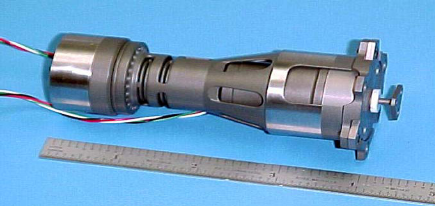
a) Dual-stage Rubicon actuator
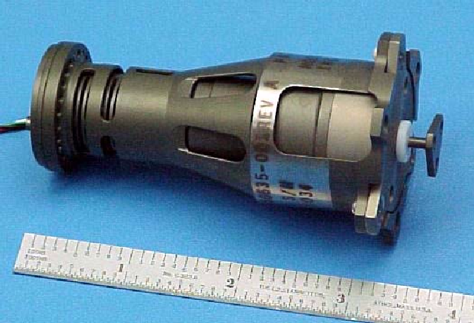
b) Single-stage Rubicon actuator
Figure 3. a) Dual-stage and b) single-stage Rubicon actuators.